#1 A different type of Engine Stand for the XK Engine
Posted: Wed Jan 31, 2018 11:22 am
XK Jaguar Engine Stand
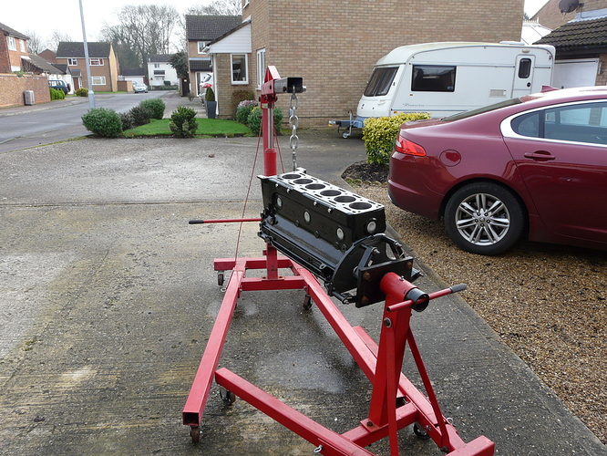
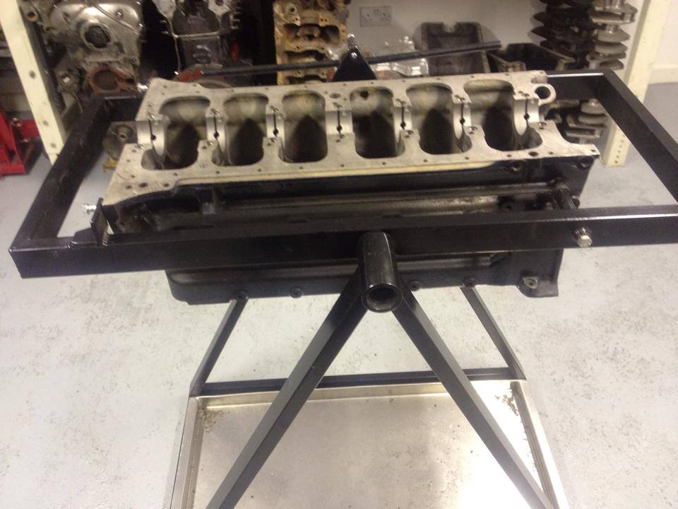
I really can't live with the massive over-hang and puny adjustable fingers you see when engines are attached longitudinally to the omni-present Machine Mart or Clarkes engine stands, particularly with an in-line six like the XK lump which frightens me enough already even when it's on the ground.
http://forum.etypeuk.com/viewtopic.php?f=3&t=9972
That exchange itself speaks volumes about why we all secretly hate the method, and the picture below confirms what we are all frightened of.
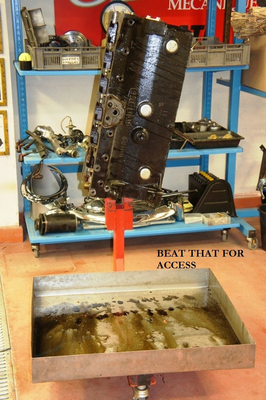
Furthermore, access is poor - working on the flanks is great, if there was anything to do there, whereas work on the all-important rear seal area in any comfort is impossible.
Worse still, the engine is dangerously imbalanced as the stand pivot sits way too close to the crankshaft centre, with the whole block poised above it, and it's even worse when the head is on as well.
I have been thinking for years that there MUST be a better way.
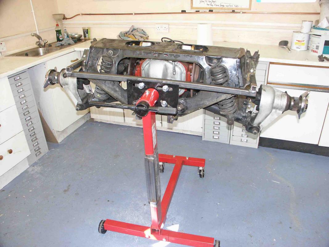
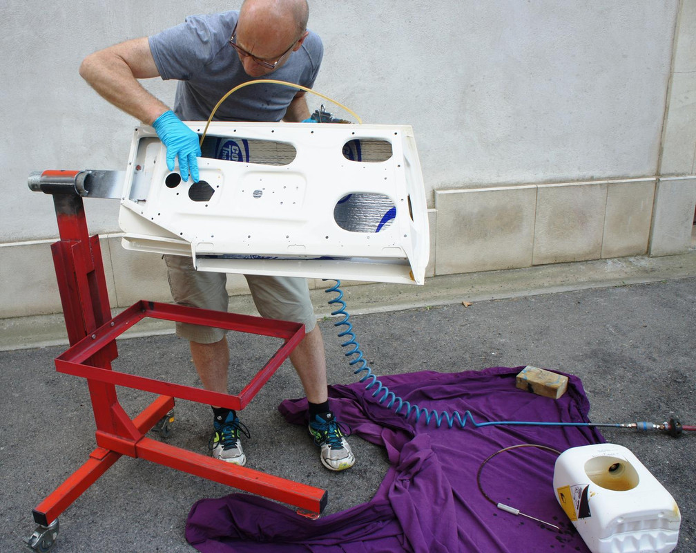
The Mini Crab I made
goes off the back of the engine, and spreads the loads widely through two-plane attachment.
In this way a 99% complete A-Series can be built up in comfort and with near-perfect balance.
All other adapters use a horrible off-set mounting on the alternator attachments on the front.
I wanted to try a similar approach and make something for the XK engine.
Note that the trick here on the Mini version is using a bung that protrudes into the fuel-pump socket, so that the 5/16 UNC bolts on either side actually don't do very much work.
Now, for the Jaguar engine, there was a rather clunky attempt posted elsewhere which turned the whole construction into a dock-yard job, with everything machined and brackets and struts bolted together.
This one, however, took me just one Sunday afternoon and requires no particularly accurate operations or machine-tools.
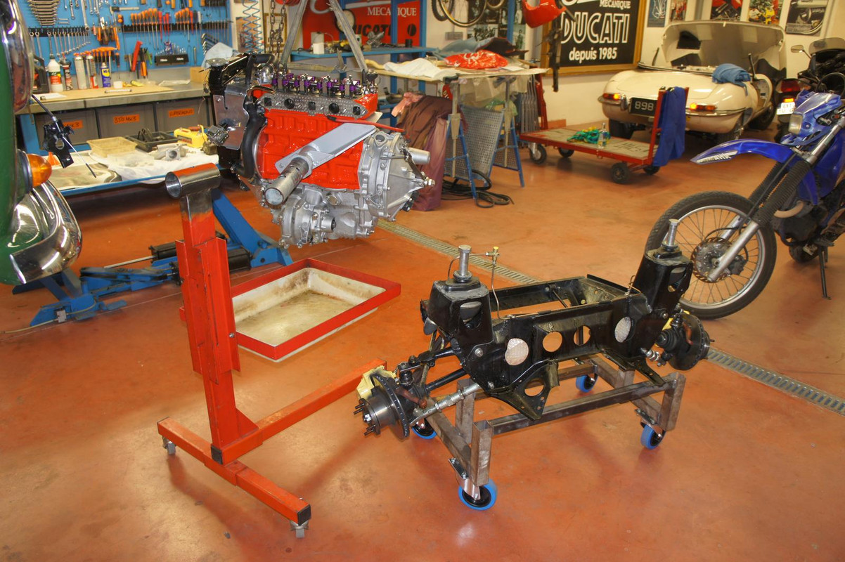
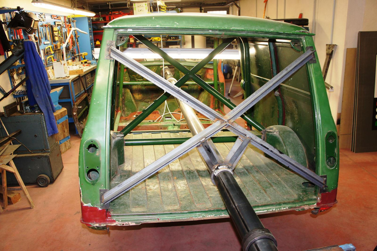
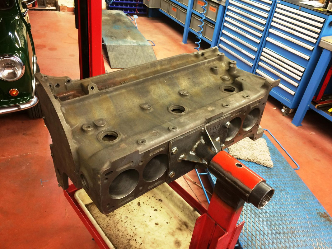
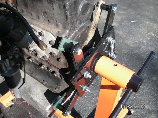
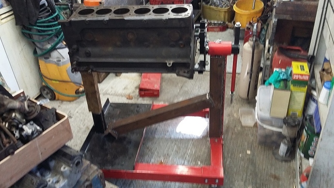
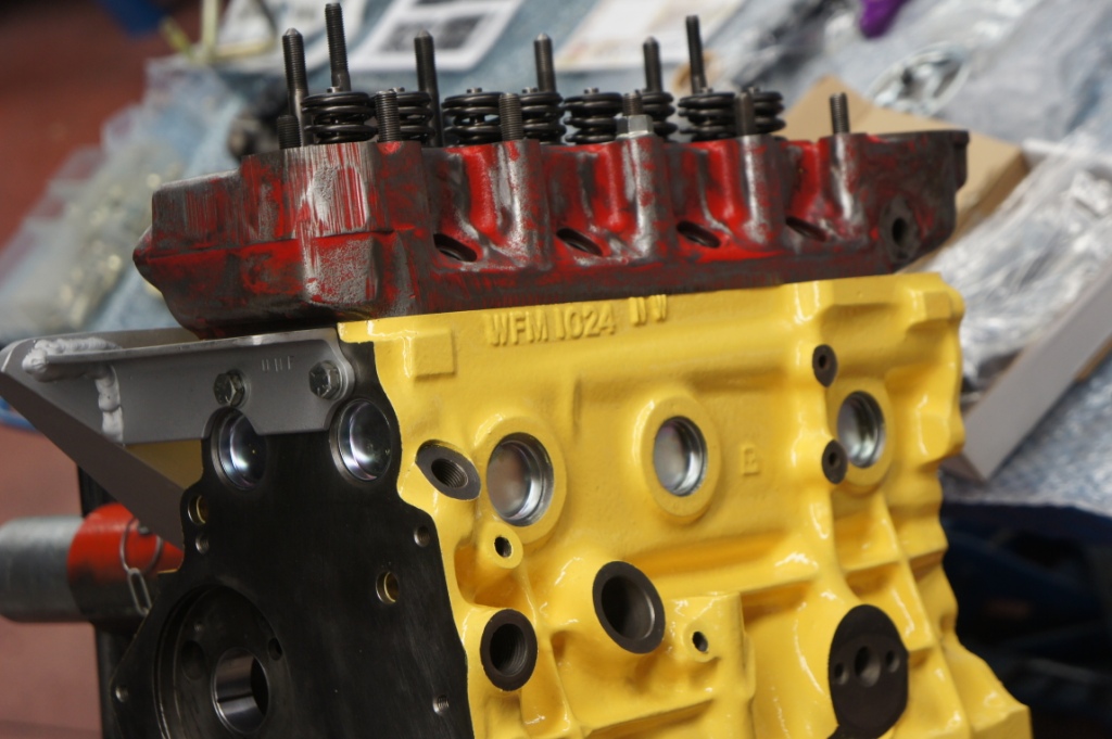
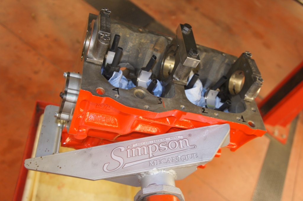
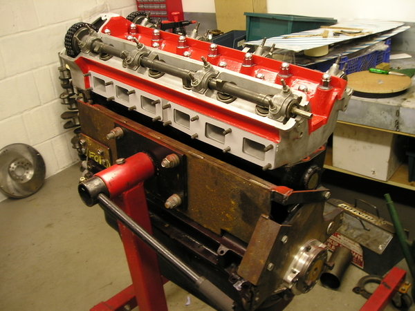
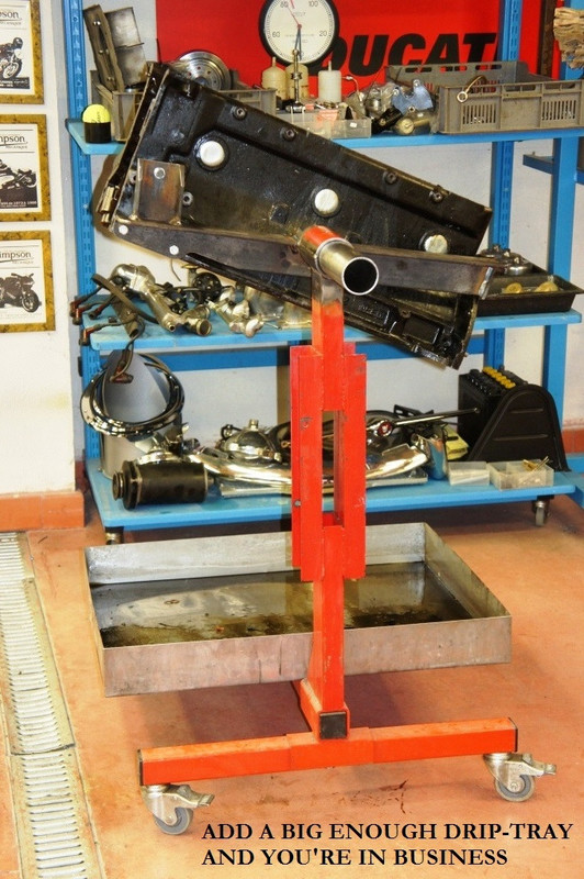
These are pictures of the result, sometimes the prototype is crap and I photograph the Mark 2 - however on this occasion it was right first time and I've just used it to completely dismantle the E-Type engine.
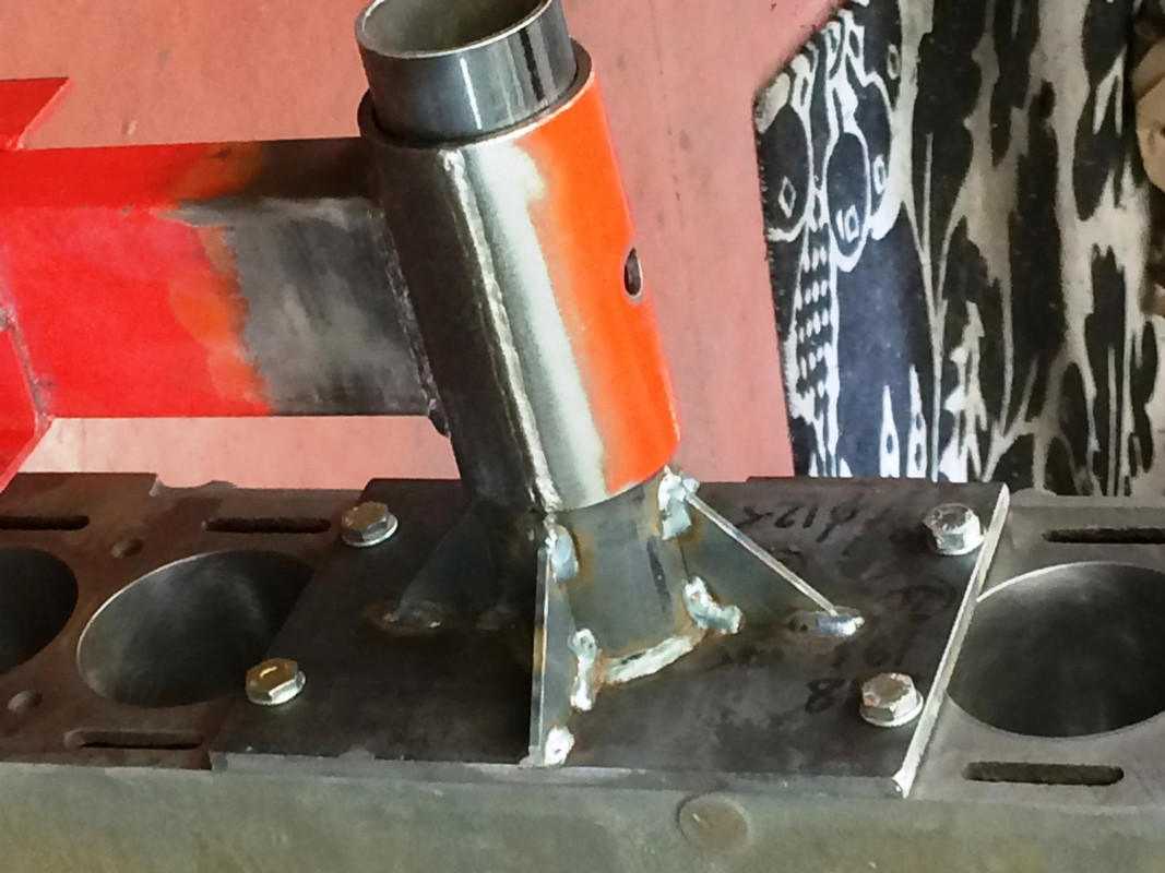
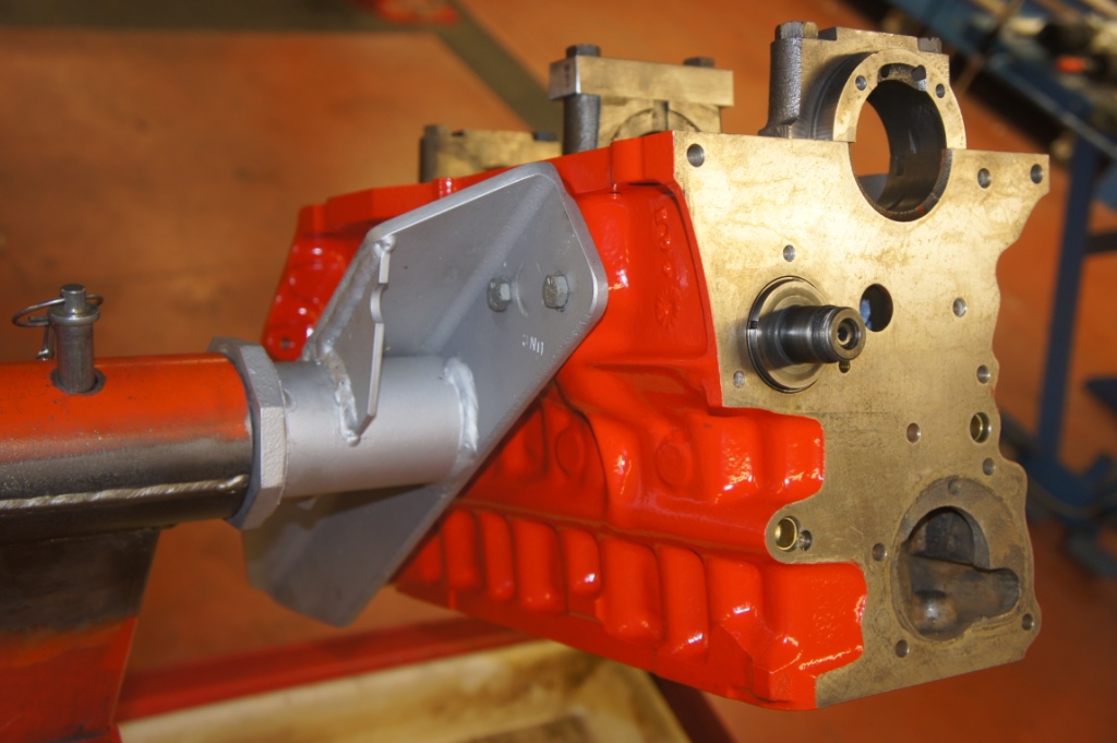
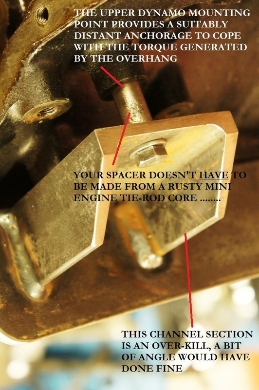
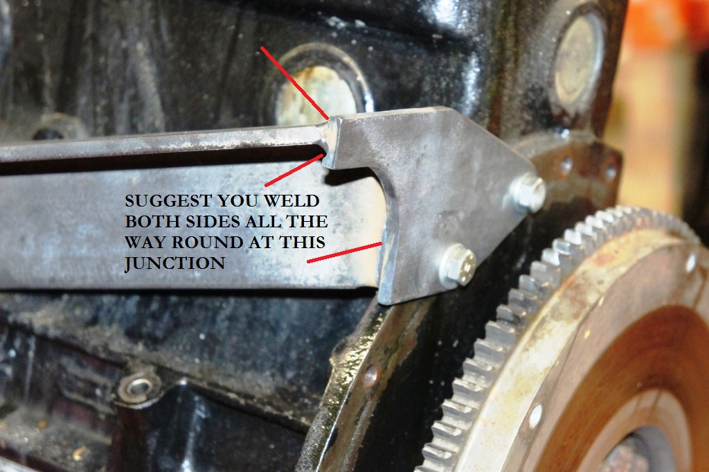
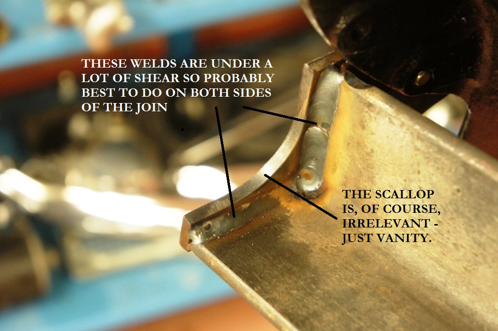
The massive torque imposed on the "crab" is comfortably coped with by the addition of the upper brace onto the dynamo/alternator mounting, and the introduction of the bell-housing plate whose bolts are working in pure shear.
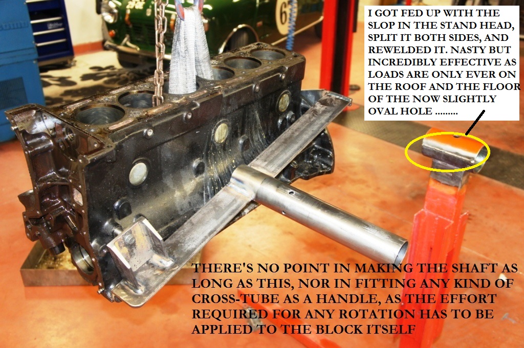
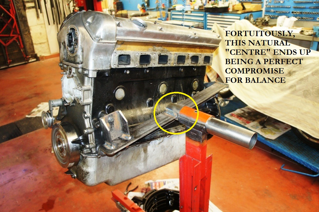
Furthermore, the loads on the head of the engine stand are greatly reduced because of the lack of over-hang, so the engine rotates easily, and - as luck would have it - the main shaft ends up in a position that seems to be a happy compromise regarding balance whatever the state of assembly or disassembly of the motor.
(Sorry about some of the 90° pictures, the new picture-software doesn't like some of my shots)
This is not intended as a How-To guide, just some suggestions that would have helped me focus on the critical issues.
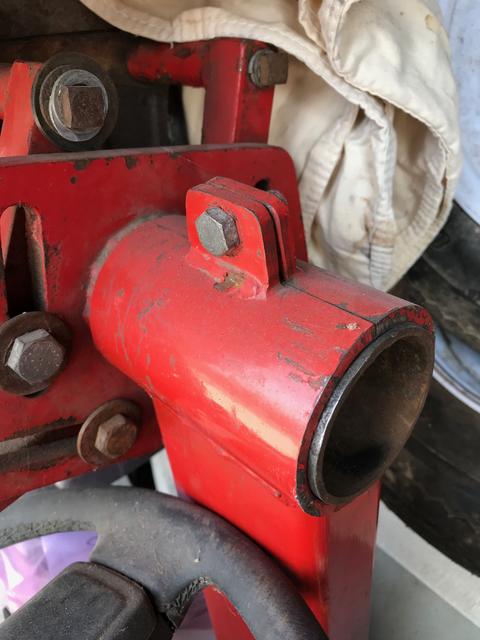
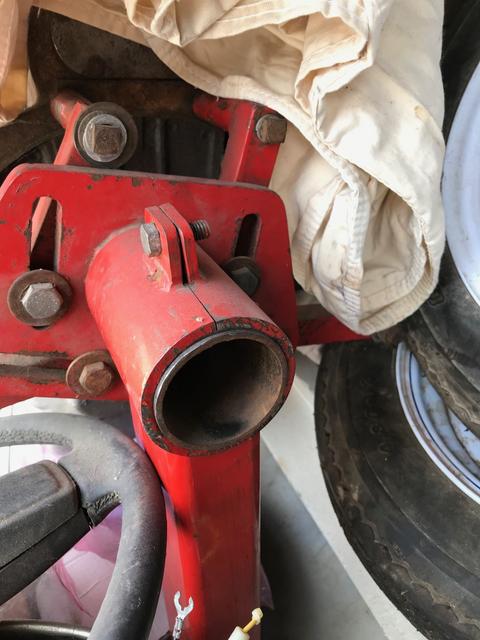
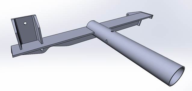
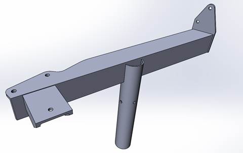
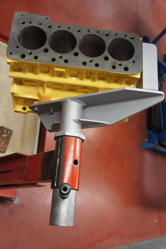
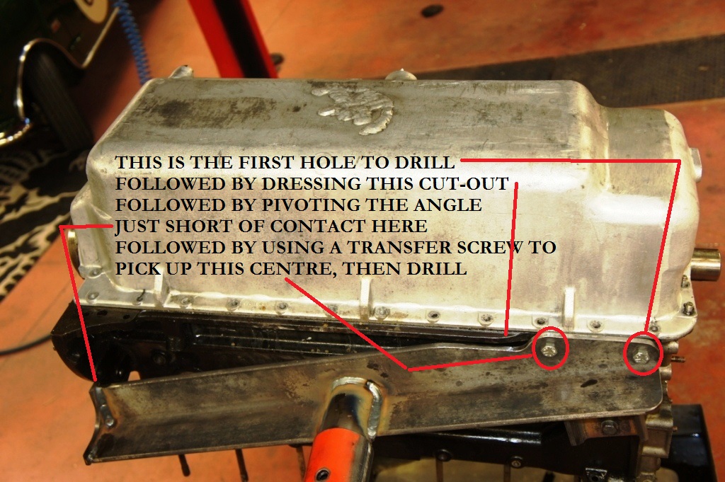
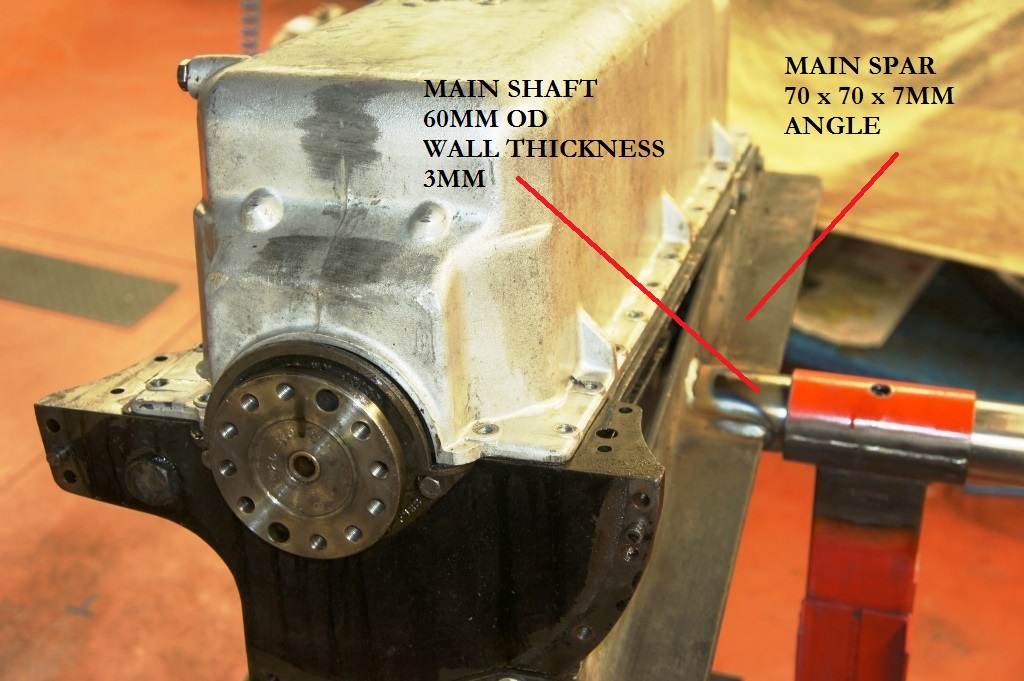
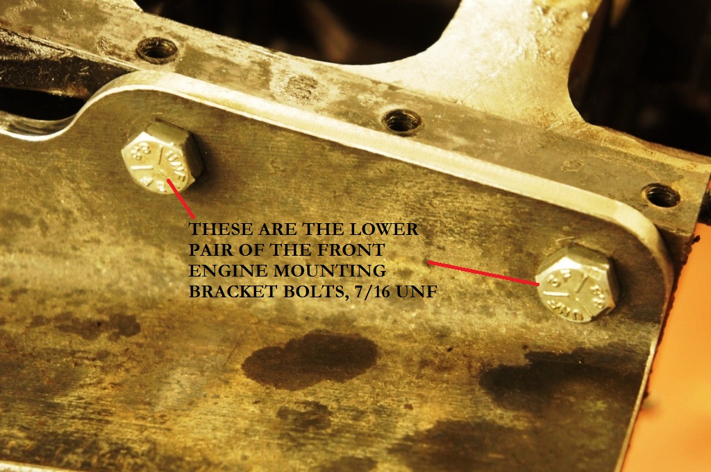
If you make the main spar so it's a few cm too long on the RH end, once it's anchored by the two lower front engine mounting 7/16" bolts you can easily project onto it the alignment of the bell-housing face at the back, using a steel-rule, and in that way cut it to the required length and at the required angle for a snug fit to the side-plate, which I cut from 8mm plate.
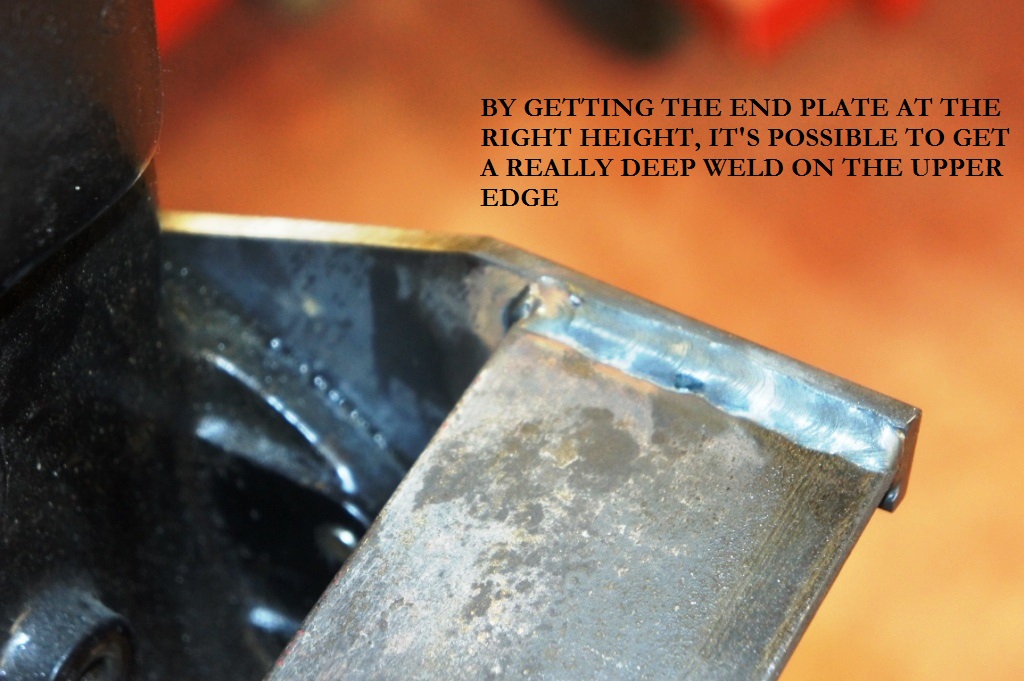
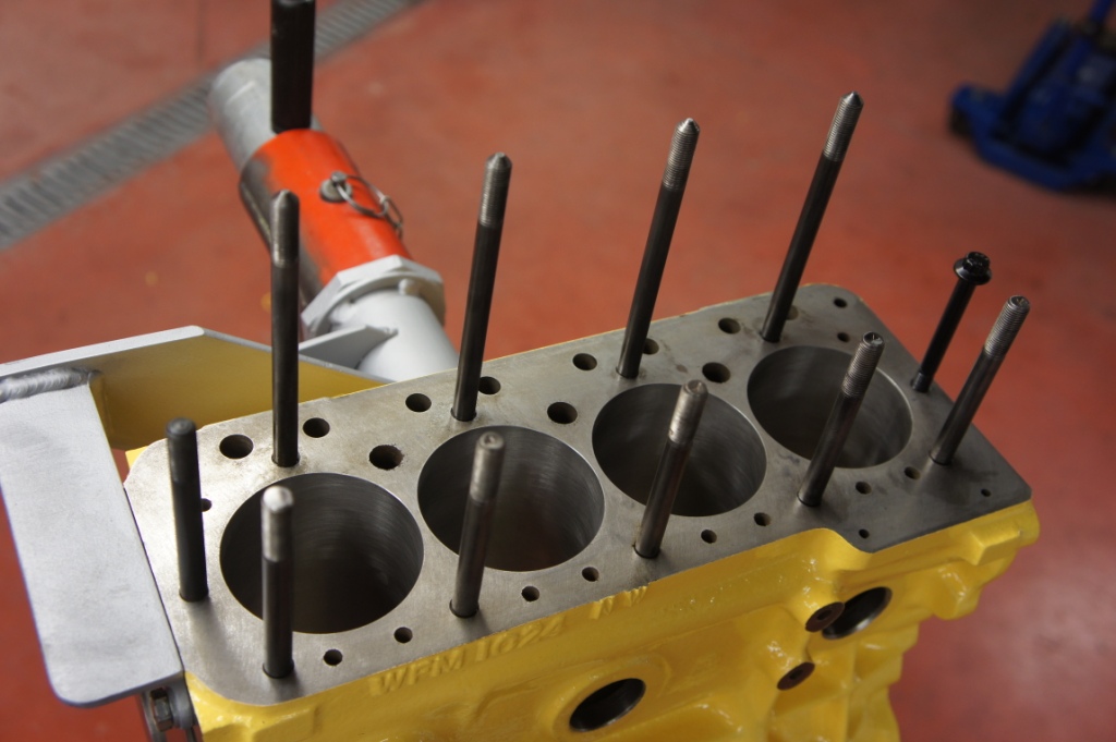
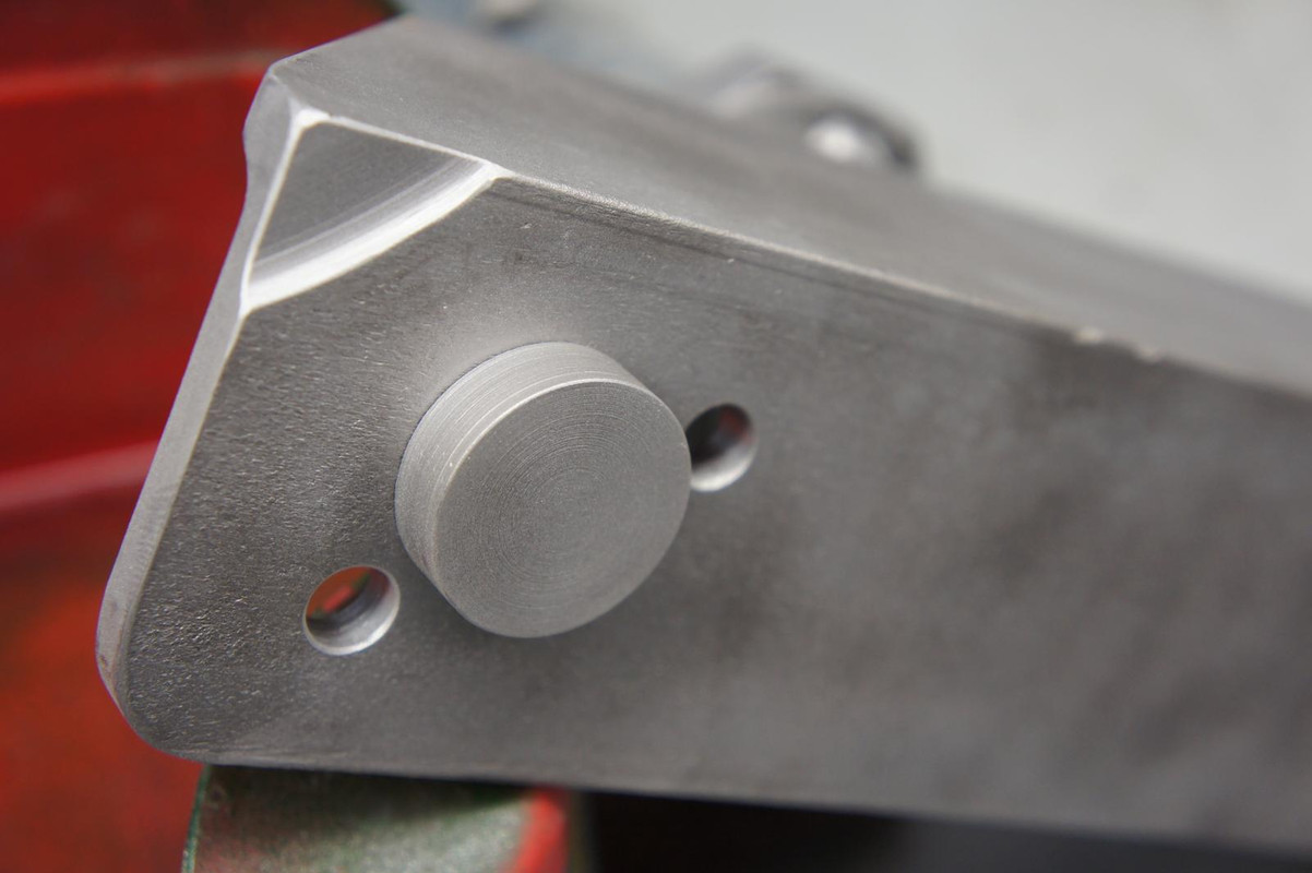
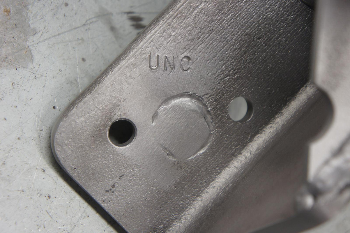
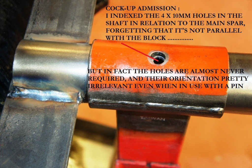
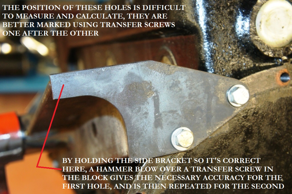
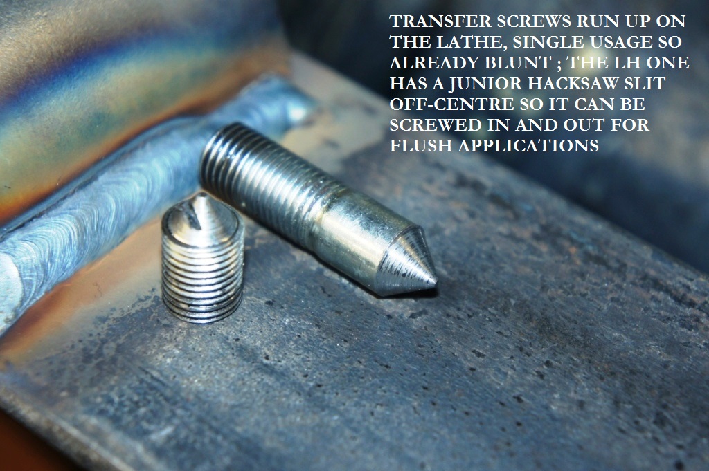
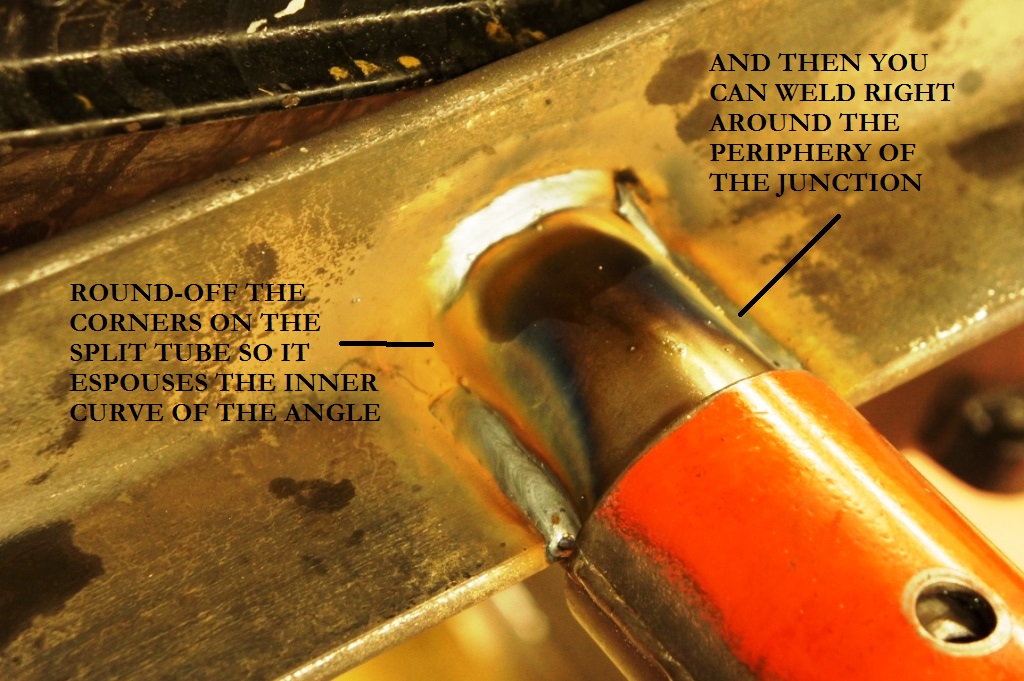
Other details : all the welded junctions were cut back 45° to give better penetration ; the pictures of the transfer screws show how to get the holes accurate without having to give them loads of slop ; careful marking and cutting of the throat slots in the main shaft makes for optimum assembly strength onto the main spar.
References elsewhere to "propping up the crank nose with a length of wooden spar" or anxieties about "what grade of bolts to use", when using the conventional long-overhang method, show just how awful that method really is.
There's perhaps an opportunity for someone to make these as a kit of parts that the purchaser could then weld together, using his own engine as a reference ; hey Dave ?!
Given the length of the jig, I'd not be 100% confident that you could make a one-size-fits all without leaving excessive slop in all the holes to cope with machining differences between different engines, but I may be worrying about nothing.
EDIT - turns out you CAN use this on EVERY XK engine, and SNGB Barratt now retail my design.
I really can't live with the massive over-hang and puny adjustable fingers you see when engines are attached longitudinally to the omni-present Machine Mart or Clarkes engine stands, particularly with an in-line six like the XK lump which frightens me enough already even when it's on the ground.
http://forum.etypeuk.com/viewtopic.php?f=3&t=9972
That exchange itself speaks volumes about why we all secretly hate the method, and the picture below confirms what we are all frightened of.
Furthermore, access is poor - working on the flanks is great, if there was anything to do there, whereas work on the all-important rear seal area in any comfort is impossible.
Worse still, the engine is dangerously imbalanced as the stand pivot sits way too close to the crankshaft centre, with the whole block poised above it, and it's even worse when the head is on as well.
I have been thinking for years that there MUST be a better way.
The Mini Crab I made
goes off the back of the engine, and spreads the loads widely through two-plane attachment.
In this way a 99% complete A-Series can be built up in comfort and with near-perfect balance.
All other adapters use a horrible off-set mounting on the alternator attachments on the front.
I wanted to try a similar approach and make something for the XK engine.
Note that the trick here on the Mini version is using a bung that protrudes into the fuel-pump socket, so that the 5/16 UNC bolts on either side actually don't do very much work.
Now, for the Jaguar engine, there was a rather clunky attempt posted elsewhere which turned the whole construction into a dock-yard job, with everything machined and brackets and struts bolted together.
This one, however, took me just one Sunday afternoon and requires no particularly accurate operations or machine-tools.
These are pictures of the result, sometimes the prototype is crap and I photograph the Mark 2 - however on this occasion it was right first time and I've just used it to completely dismantle the E-Type engine.
The massive torque imposed on the "crab" is comfortably coped with by the addition of the upper brace onto the dynamo/alternator mounting, and the introduction of the bell-housing plate whose bolts are working in pure shear.
Furthermore, the loads on the head of the engine stand are greatly reduced because of the lack of over-hang, so the engine rotates easily, and - as luck would have it - the main shaft ends up in a position that seems to be a happy compromise regarding balance whatever the state of assembly or disassembly of the motor.
(Sorry about some of the 90° pictures, the new picture-software doesn't like some of my shots)
This is not intended as a How-To guide, just some suggestions that would have helped me focus on the critical issues.
If you make the main spar so it's a few cm too long on the RH end, once it's anchored by the two lower front engine mounting 7/16" bolts you can easily project onto it the alignment of the bell-housing face at the back, using a steel-rule, and in that way cut it to the required length and at the required angle for a snug fit to the side-plate, which I cut from 8mm plate.
Other details : all the welded junctions were cut back 45° to give better penetration ; the pictures of the transfer screws show how to get the holes accurate without having to give them loads of slop ; careful marking and cutting of the throat slots in the main shaft makes for optimum assembly strength onto the main spar.
References elsewhere to "propping up the crank nose with a length of wooden spar" or anxieties about "what grade of bolts to use", when using the conventional long-overhang method, show just how awful that method really is.
There's perhaps an opportunity for someone to make these as a kit of parts that the purchaser could then weld together, using his own engine as a reference ; hey Dave ?!
Given the length of the jig, I'd not be 100% confident that you could make a one-size-fits all without leaving excessive slop in all the holes to cope with machining differences between different engines, but I may be worrying about nothing.
EDIT - turns out you CAN use this on EVERY XK engine, and SNGB Barratt now retail my design.