


Good morning all,
While my rear cage is “down and out” I’m considering changing the output shaft bearing seals.
My question is how easy is it to remove and replace the bearings which I assume you have to do to get to the seals.
Is this a home garage job ?
Thanks
Tim
Output shaft bearings
#1 Output shaft bearings
Series 1 FHC purchased 40 years ago. Courted my wife in it.
Series 1 2+2 when the kids were small now sold.
Series 1.5 OTS in opalescent maroon, Californian car. My retirement present.
Series 1 2+2 when the kids were small now sold.
Series 1.5 OTS in opalescent maroon, Californian car. My retirement present.
| Link: | |
| BBcode: | |
| HTML: | |
| Hide post links |

#2 Re: Output shaft bearings
Hi Tim...probably not the same diff as yours but on my 69 S2 2+2 have done this twice...it still leaks....spoke to Alan Slawson who recomended replaceing the o/p shaft unit with xjs units....they are still sitting on the shelf waiting for me to fit.....on my new build i just opted to have the diff check over by Universal axles. Kidderminster they found slight scoring on tbe o/p shafts so had them machined....it isnt difficult replaceing tbe seals an easy diy job....but stopping it leaking is another thing..........best to identify what type of diff you have fitted, there are 3 types...yours may be easyer. ... Steve
Steve
69 S2 2+2 (just sold) ..Realm C type replica, 1960 xk150fhc
69 S2 2+2 (just sold) ..Realm C type replica, 1960 xk150fhc
| Link: | |
| BBcode: | |
| HTML: | |
| Hide post links |
#3 Re: Output shaft bearings
Thanks Steve,
Do the bearings come off without a puller ( which I don’t have -yet) .
The manual suggests just undoing the nut, remove tab washer and slide the bearing off !
Tim
Do the bearings come off without a puller ( which I don’t have -yet) .
The manual suggests just undoing the nut, remove tab washer and slide the bearing off !
Tim
Series 1 FHC purchased 40 years ago. Courted my wife in it.
Series 1 2+2 when the kids were small now sold.
Series 1.5 OTS in opalescent maroon, Californian car. My retirement present.
Series 1 2+2 when the kids were small now sold.
Series 1.5 OTS in opalescent maroon, Californian car. My retirement present.
| Link: | |
| BBcode: | |
| HTML: | |
| Hide post links |
#4 Re: Output shaft bearings
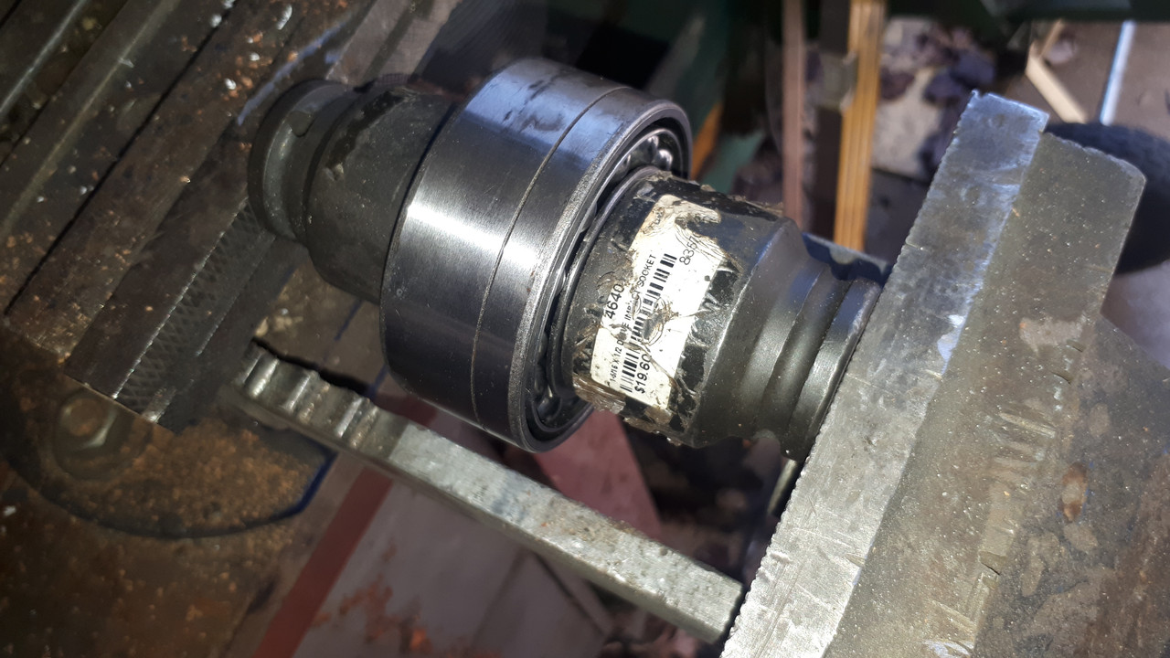
I, like Steve, have the type three diff with the output shaft where the drive flange is directly attached to the output shaft (no nut) and it certainly is easy to replace the seal. Once you've undone the flange/caliper attachment plate on the side of the diff the shaft and bearing, flange and shaft will just slide out.
Mark the bearing retaining nut so you can return it to the same place on reassembly and remove. If you haven't got a spanner/adjustable large enough for the bearing retaining nut, grip the nut in a vice and use a bar between the disc retaining blots to undo the nut. The only thing to be careful over is as you drift the shaft out of the bearing your balls from the bearing can escape and go everywhere - 13 iirc Keep the inner and outer races together and you'll be fine and use a cloth or similar to contain them if they do try to escape. No puller or special tools needed.
Mark the bearing retaining nut so you can return it to the same place on reassembly and remove. If you haven't got a spanner/adjustable large enough for the bearing retaining nut, grip the nut in a vice and use a bar between the disc retaining blots to undo the nut. The only thing to be careful over is as you drift the shaft out of the bearing your balls from the bearing can escape and go everywhere - 13 iirc
John
1969 Series 2 FHC
1969 Series 2 FHC
| Link: | |
| BBcode: | |
| HTML: | |
| Hide post links |
#5 Re: Output shaft bearings
Tim....one thing i was advised by Alan Slawson is that original bearings for my type 3 diff (dont know if its the same for others) are no longer available and the aftermarket replacements have less balls and poor quality...so dont just replace becaus you have it apart.....he told me he hadnt seen a diff that actually needed them replaceing

Steve
69 S2 2+2 (just sold) ..Realm C type replica, 1960 xk150fhc
69 S2 2+2 (just sold) ..Realm C type replica, 1960 xk150fhc
| Link: | |
| BBcode: | |
| HTML: | |
| Hide post links |

#6 Re: Output shaft bearings
Hello Steve,
The original output bearings you refer to are double row, angular contact, ball bearing type, where the inner race is made in two halves with a slight gap between the inner ends (designed pre-load clearance) when the bearing is assembled and held together with just hand pressure. The Inner race halves are brought together until their inner ends are in firm contact when the nut holding the bearing to the shaft is tightened, thus pre-loading the bearing.
The original bearing is 29mm wide and the normal replacement, having the same OD and ID dimensions, is only 27mm wide, has a solid inner race and can't be pre-loaded as can the the original style. This bearing requires a 2mm wide space between the end of the inner race and the shoulder of the output shaft it contacts and another 2mm spacer between the end of the outer race and the plate that triples as a brake caliper mount, bearing securing plate and oil seal holder. The spacers have to go on the outboard end of the bearing (seal flange end) so that the bearing is held firm against the bottom of the bore into which it fits. The reason it needs to go to the bottom of the bore, is that there is an "O" ring to seal against oil leaking between the OD of the bearing and the ID of the bore, positioned roughly 5mm from the bottom of the bore.
A better arrangement for the 2mm spacers would be just one spacer placed at the bottom of the bore for the outer race and no spacer for the inner race (not required in this arrangement). This would allow the Outer Oil Seal to kiss the end face of the outer race instead of a spacer that would be between the bearing and the seal in the normal arrangement when the 27mm wide bearing is used. The problem with putting the spacer at the bottom of the bore, is that the radius between the face and OD surface of the bearing starts to encroach on the "O" ring near the bottom of the bore, rendering it ineffective. I opt for the single spacer at the bottom of the bore, but I set the Diff Housing up in a Machining Centre and machine a new "O' ring groove to ensure a good seal by the "O" ring in this arrangement.
Every time I have to order output shaft bearings, I go through the process of searching for the correct style and on every occasion the result has been that the original style is unavailable. That was until just last week when my bearing supplier found a source in the U.S.A. I haven't got one in my hand yet, but will have in the next few days. They are not cheap (AUD300.00 each), but they seem to be the correct style.
The diffs used on Series 1 cars use a much better bearing arrangement than the later cars and a much, much better system of pre-loading the pinion shaft bearings. I doubt that anyone involved would have suggested, when changing to the system used in the S2 and S3 diffs, here is a much better system, but more likely, here is a cheaper, cost saving system.
In either system, the output shaft oil seals are not that difficult to replace, except for the removal of the old seal from it's carrier. If the bearings are not being replaced, the output shaft assemblies can be dismantled, the seals replaced and all assembled as they were prior to dismantling. Take care to retain the shim stack for each output shaft assembly and reassemble with same.
Regards
Bill
| Link: | |
| BBcode: | |
| HTML: | |
| Hide post links |
#7 Re: Output shaft bearings
As always Bill a very professional detailed explanation. ....many thanks..... Steve
Steve
69 S2 2+2 (just sold) ..Realm C type replica, 1960 xk150fhc
69 S2 2+2 (just sold) ..Realm C type replica, 1960 xk150fhc
| Link: | |
| BBcode: | |
| HTML: | |
| Hide post links |
#8 Re: Output shaft bearings
Thanks to all. I will let you know how I get on. A way to yet.
If Monday is fine enough I will be jet washing the cage and doff to remove 50 years of oil, grease and whatever !
Tim
If Monday is fine enough I will be jet washing the cage and doff to remove 50 years of oil, grease and whatever !
Tim
Series 1 FHC purchased 40 years ago. Courted my wife in it.
Series 1 2+2 when the kids were small now sold.
Series 1.5 OTS in opalescent maroon, Californian car. My retirement present.
Series 1 2+2 when the kids were small now sold.
Series 1.5 OTS in opalescent maroon, Californian car. My retirement present.
| Link: | |
| BBcode: | |
| HTML: | |
| Hide post links |

#9 Re: Output shaft bearings
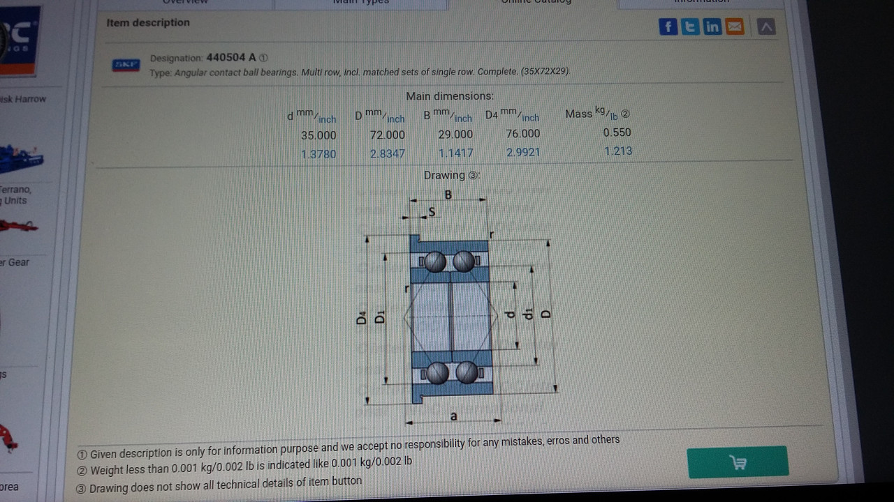
Hello Bill, my turn now. I may have found a possibility, is it the same?angelw wrote: ↑Sun Feb 04, 2018 11:25 amEvery time I have to order output shaft bearings, I go through the process of searching for the correct style and on every occasion the result has been that the original style is unavailable. That was until just last week when my bearing supplier found a source in the U.S.A.
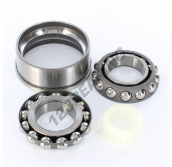
440504 are double row angular contact ball bearings with split inner rings, ID x OD x width = 35 x 72 x 29 mm.
Bloke down in Melb has three for sale, trouble is they are flanged, i don't know if there are unflanged versions available, I could maybe try getting the flanges ground off ...
Regards,
ColinL
'72 OTS manual V12
ColinL
'72 OTS manual V12
| Link: | |
| BBcode: | |
| HTML: | |
| Hide post links |
#10 Re: Output shaft bearings
Colin Wrote:
The ID Number of the correct bearing is 414444A and has no flange.
The flange on the bearings you're referring to could be machined off and it wouldn't matter if the area was machined slightly under. It would be quicker to turn the flange off with Carbide or CBN Inserts, rather than by grinding.
Get them sent to the workshop and I'll machine them if you like.
Regards,
Bill
Hello Colin,Bloke down in Melb has three for sale, trouble is they are flanged, i don't know if there are unflanged versions available, I could maybe try getting the flanges ground off ...
The ID Number of the correct bearing is 414444A and has no flange.
The flange on the bearings you're referring to could be machined off and it wouldn't matter if the area was machined slightly under. It would be quicker to turn the flange off with Carbide or CBN Inserts, rather than by grinding.
Get them sent to the workshop and I'll machine them if you like.
Regards,
Bill
| Link: | |
| BBcode: | |
| HTML: | |
| Hide post links |
#11 Re: Output shaft bearings
Hello Colin,
The sealing system and the manner in which the bearing is held in position is flawed.
I suspect that you will see evidence of the previous bearings having spun in their respective housings of your differential; I've not worked on an E Type differential that used the double row, angular contact bearing , where this hasn't been the case. The square section "O" ring and and the 0.003" compression of the outer seal against the outer face of the bearing is all that's being relied upon to stop the bearing from spinning; a big ask particularly when the original bearing and the 440504 bearing you're contemplating on using are in pre-load when in use.
The manual states that a 0.003" crush of the seal has been allowed for when calculating the shim stack to use between the caliper mounting bracket and the differential housing. However, the seal protrudes a good 1.0mm plus, from the inside face of the seal housing; accordingly its only the 0.003" crush of the seal that makes any contact with the bearing. What is be a better proposition is to have the inner face of the seal housing (the inner part of the caliper bracket) bear hard against the face of the outer race of the bearing and the seal to protrude just enough to result in the circa 0.003" crush. When the correct bearing was available and later on with the 2.0mm narrower bearing and the 2.0mm spacers, I machined the bore for the seal deeper so that the seal only protruded 0.003" -0.0 + 0.002. In application, the seal would crush the circa 0.003" before the inner face of the caliper bracket came up against the face of the outer race of the bearing to lock it in place between it and the bottom of the bore for the bearing.
Regards,
Bill
| Link: | |
| BBcode: | |
| HTML: | |
| Hide post links |
#12 Re: Output shaft bearings
Thx Bill. My originals were 414444 i.e. without the “A” suffix which i understand usually denotes a mostly harmless internal mod? The 440504’s will be sent to you, just as soon as he can sneak to the post office ...
No evidence that my bearings had spun in their housings. I reckon for such double roller bearings to be so stiff (stuffed), that they would move (rotate) in their housings, is probably a good part of why the cars end up in your workshop.
I also don’t reckon you could preload these bearings enough to make them stiffen. Imo the split inner ring is not for pre-loading, clamping them together with maximum force just gives zero pre-load. In this regard I see nothing wrong with the SNGB not-split bearing. However, the reason bearings have split rings is because it enables the bearing to be constructed with more balls which directly increases the load bearing capacity. It is why 414444 and 440504’s have 26 balls while the substitutes that SNGB sells (3207/5207) have only 18 balls. In this regard I have a big issue with the SNGB solution, it can only have substantially less load bearing capacity and hence longevity compared to the original Jaguar design.
Absolutely I agree that as far as sealing goes the OEM design is flawed. Since when was the bottom outer end of a radial seal a designated sealing surface? I can’t image any seal OEM ever agreeing to warrant that. No wonder these seals were originally never available separately. In my case the seals supplied by SNGB protrude only 0.3 mm, nevertheless achieving 0.076 mm (0.003”) squash is impossible because there is nothing to squash against. The seal is supposed to squash against the edge of the bearing outer ring. The ends of both the bearing outer ring and the rubber seal have small chamfers. After allowing for these, the OD of the rubber seal and the ID of the bearing outer ring are both 67 mm, i.e the seal surfaces completely miss, there is no seal face contact at all. No wonder there are leaks.
Sealing-wise the SNGB offering has potential merit, the more expensive bearing is sealed, imo only the outer side should have a seal. Also the spacer ring must be wide enough to extend to under the seal, the spacer ring ID would need to be less than 63 mm.
In my case I will need to achieve a seal between the bearing outer ring and the metal edge of the seal housing/brg retainer (the part that Jaguar erroneously calls a caliper mounting bracket). Here there is the same problem but to a lesser extent. After allowing for chamfers, the ID of the housing is 68.6 mm and the OD of the bearing is 70.5 mm, leaving less than 0.5 mm width of mating surfaces to make a seal. Imo for this a thin bead of silicone gasket material will be the perfect solution.
The shims between the seal housing/bearing retainer and the diff housing, better to not use any than to put in too many, the latter would leave the bearing loose and cause leaks for sure, the former would do no harm whatsoever.
Woderyerekan?
And why, I wonder, is the square section o-ring so-called? The ones I took out were not square section, just circular section. And the ones SNGB sold me also just circular section...
Regards,
ColinL
'72 OTS manual V12
ColinL
'72 OTS manual V12
| Link: | |
| BBcode: | |
| HTML: | |
| Hide post links |
#13 Re: Output shaft bearings
Hello Colin,
I agree with most of what you have written, but not that the 414444 bearing are not pre-loaded when the two halves of the inner race are clamped together. I've handled many, new, original 414444 bearings, when they were available, over the years and by accurate measurement its easily determined that the bearing will be in pre-load when the inner halves are drawn together. In a past life I services precision spindle modules for CNC machine tools; all of which have bearing arrangements that result in the bearings being in pre-load. Generally, the arrangement was angular contact P4 (or better) bearings in pairs in a Back to Back, or Front to Front configuration. Although the bearings are supplied in matched sets, I would always measure the bearings individually and stacked to ensure that the pre-load was going to be in spec. My habits didn't change when I started working on differentials and gearboxes.
The original "O" ring used in the bore for the Output Shaft assembly, is square section. If the "O" ring you retrieved from your differential was round, that simply means that someone has been there before you and replaced the "O" ring with the incorrect round section. SNGB and others that supply a round section "O" ring as a replacement, are just supplying what is easiest to obtain, not what is correct.
You would have to agree that the OD of the Output Shaft bearing is a running fit in its respective bore; you would have had no trouble removing the assembly from the differential housing, with no puller being required. The only things that stops the bearing spinning in the bore is the friction between the bearing OD and the two sealing devices and a bit of suck between the bearing OD and diff housing bore if the bearing was lubricated during assembly.
Regards,
Bill
| Link: | |
| BBcode: | |
| HTML: | |
| Hide post links |
#14 Re: Output shaft bearings
Ok. My maximum force just wasn't enough. Put it in the vice and tightened with a sledge hammer, that stopped it free-wheeling.
Whatever its propensity to rotate, I reckon the main reason it shouldn't is the axial clamping force applied by the seal holder/brg retainer. Unless its been over-shimmed, then its not clamping anything, would also leak
Whatever its propensity to rotate, I reckon the main reason it shouldn't is the axial clamping force applied by the seal holder/brg retainer. Unless its been over-shimmed, then its not clamping anything, would also leak
Regards,
ColinL
'72 OTS manual V12
ColinL
'72 OTS manual V12
| Link: | |
| BBcode: | |
| HTML: | |
| Hide post links |
#15 Re: Output shaft bearings
Attaboy!
Andrew.
881824, 1E21538. 889457. 1961 4.3l Mk2. 1975 XJS. 1962 MGB
http://www.projectetype.com/index.php/the-blog.html
Adelaide, Australia
881824, 1E21538. 889457. 1961 4.3l Mk2. 1975 XJS. 1962 MGB
http://www.projectetype.com/index.php/the-blog.html
Adelaide, Australia
| Link: | |
| BBcode: | |
| HTML: | |
| Hide post links |
#16 Re: Output shaft bearings
I agree with the ultimate advice given in all the other posts on this subject throughout our forum, that the best solution is to replace the S3 e-type output shaft assemblies with parts from an XJ. Great if you can get them, I’d have to steal the whole car. Which is why I’m paying 400 dollars for a couple of discontinued roller bearings. The frustrating thing is, I did have a car, the donor for my HE engine, but I sold the IRS to some eager hot-rodders. Output shafts, 2.88 diff, 4 pot callipers... damn. Still, if that car had been hanging around for as long as it has taken me to get around to it, I would doubtless be living by myself....
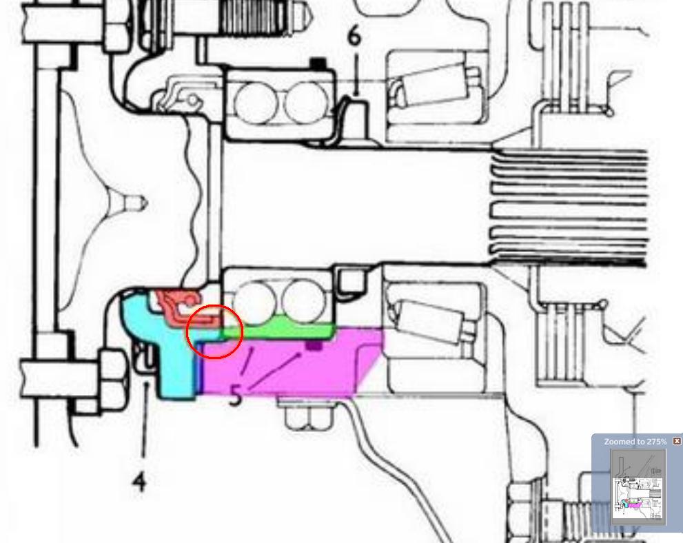
Here it is to scale in glorious technicolor, measured with vernier callipers and a magnifying glass. The diff is pink, bearing (outer ring) is green, seal is red and the seal housing (Jaguar’s “caliper bracket”) is light blue, the shims are dark blue. The marked up extract from the manual is to show where we are at.
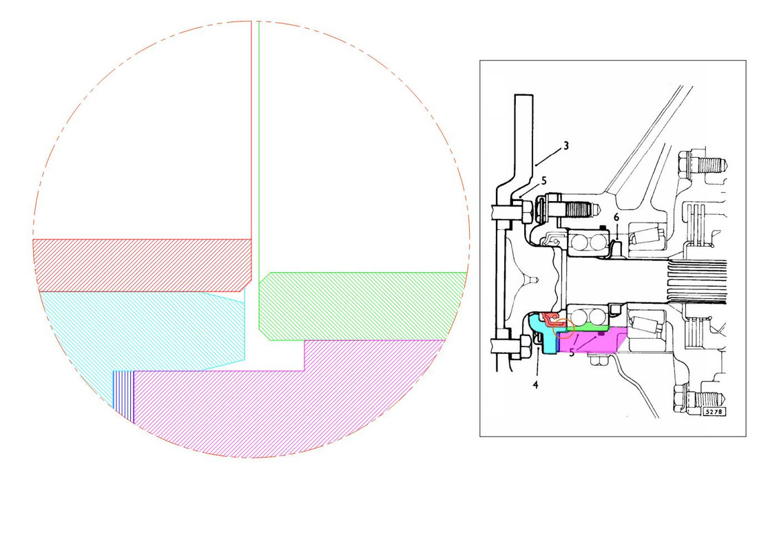
The objective is, in effect, to close the gap under the bearing by reducing the number of shims. The manual says to close the gap between the green and the red. Imo bad design, won’t work, any seal contact surface would be too small and unreliable, it will leak, bearings not positively restrained, could move axially and even rotate, exacerbating leakage and premature failure. Imo the only viable solution, you must hard-close the gap between the green and the light blue, liberally coat with Hylomar (not silicone), remove the shims and torque away, only limitation the tensile strength of the bolts.
Here it is to scale in glorious technicolor, measured with vernier callipers and a magnifying glass. The diff is pink, bearing (outer ring) is green, seal is red and the seal housing (Jaguar’s “caliper bracket”) is light blue, the shims are dark blue. The marked up extract from the manual is to show where we are at.
The objective is, in effect, to close the gap under the bearing by reducing the number of shims. The manual says to close the gap between the green and the red. Imo bad design, won’t work, any seal contact surface would be too small and unreliable, it will leak, bearings not positively restrained, could move axially and even rotate, exacerbating leakage and premature failure. Imo the only viable solution, you must hard-close the gap between the green and the light blue, liberally coat with Hylomar (not silicone), remove the shims and torque away, only limitation the tensile strength of the bolts.
Regards,
ColinL
'72 OTS manual V12
ColinL
'72 OTS manual V12
| Link: | |
| BBcode: | |
| HTML: | |
| Hide post links |
#17 Re: Output shaft bearings
Hi Colin.....nice blow up diagram clearly showing the problem. .....i raised this issue over 10 years ago on the forum trying to solve a leaky diff on my S2 2+2..same diff as yours.....problem was that there wasnt anyone around then that actually tackled diffs themselfs...so was on my own.....3 times i stripped it down trying to work out what id done wrong.........you also need to be aware of the drain chanel if your going to use sealant....the channel is in the caliper mount flange and the diff face it mates to.....too much sealant and you block it up.....the channel allows any oil that past the o/p shaft to collect and drain through chanels to under the diff rather than spraying onto the disc........after living with the oil leaks for years i then discovered the later o/p shaft option.....it solved the problem...all the best......Steve PS this post shows drain channels http://forum.etypeuk.com/viewtopic.php? ... 942#p89942
Steve
69 S2 2+2 (just sold) ..Realm C type replica, 1960 xk150fhc
69 S2 2+2 (just sold) ..Realm C type replica, 1960 xk150fhc
| Link: | |
| BBcode: | |
| HTML: | |
| Hide post links |
#18 Re: Output shaft bearings
Colin Wrote:
Its the nut securing the bearing to the Output Shaft that applies the force to pre-load the bearing. The thread diameter relative to the pitch of the thread results in a helix angle that has considerable mechanical advantage. Your vice has a fairly large helix angle and I'm not surprised you would need to use brute force with a sledge hammer to take up the clearance between the two halves of the inner race. The fact that you were able to stop the bearing from free-wheeling is proof that the bearing can be pre-loaded.
Regards,
Bill
Hello Colin,My maximum force just wasn't enough. Put it in the vice and tightened with a sledge hammer, that stopped it free-wheeling.
Its the nut securing the bearing to the Output Shaft that applies the force to pre-load the bearing. The thread diameter relative to the pitch of the thread results in a helix angle that has considerable mechanical advantage. Your vice has a fairly large helix angle and I'm not surprised you would need to use brute force with a sledge hammer to take up the clearance between the two halves of the inner race. The fact that you were able to stop the bearing from free-wheeling is proof that the bearing can be pre-loaded.
Regards,
Bill
| Link: | |
| BBcode: | |
| HTML: | |
| Hide post links |
#19 Re: Output shaft bearings
Colin Wrote:
The area shown enclosed in the Red Circle following seems to indicate that both the face of the seal and the face of the seal housing adjacent to the face of the seal, are in contact with the bearing and is the same depicted in the E Type workshop manual. Also shown in the workshop manual is a close scale of the amount the seal protrudes out past the face of the seal holder; something in the order of 1.0mm (0.040"). Given that the manual states that the calculation of the shim stack takes into account for a 0.003" squash of the seal, no doubt by measuring the gap for the shims with the seal housing bolts only done up finger tight, and there is circa 0.040" protrusion of the seal, there is zero scope for the face of the seal holder to exert any pressure on the bearing and 0.003" squash of the seal I believe will be short lived.
We're on the same page with regards to bringing the end face of the seal holder into firm contact with the bearing; I stated as much in an earlier Post in this Thread.
Regards,
Bill
Hello Colin,The objective is, in effect, to close the gap under the bearing by reducing the number of shims. The manual says to close the gap between the green and the red. Imo bad design, won’t work, any seal contact surface would be too small and unreliable, it will leak, bearings not positively restrained, could move axially and even rotate, exacerbating leakage and premature failure. Imo the only viable solution, you must hard-close the gap between the green and the light blue, liberally coat with Hylomar (not silicone), remove the shims and torque away, only limitation the tensile strength of the bolts.
The area shown enclosed in the Red Circle following seems to indicate that both the face of the seal and the face of the seal housing adjacent to the face of the seal, are in contact with the bearing and is the same depicted in the E Type workshop manual. Also shown in the workshop manual is a close scale of the amount the seal protrudes out past the face of the seal holder; something in the order of 1.0mm (0.040"). Given that the manual states that the calculation of the shim stack takes into account for a 0.003" squash of the seal, no doubt by measuring the gap for the shims with the seal housing bolts only done up finger tight, and there is circa 0.040" protrusion of the seal, there is zero scope for the face of the seal holder to exert any pressure on the bearing and 0.003" squash of the seal I believe will be short lived.
We're on the same page with regards to bringing the end face of the seal holder into firm contact with the bearing; I stated as much in an earlier Post in this Thread.
Regards,
Bill
| Link: | |
| BBcode: | |
| HTML: | |
| Hide post links |
#20 Re: Output shaft bearings
Searched online for a diagram of the 440504 bearing...could only find this one 440504 A is it the same? ...Diagram dosnt show it as a crushable center?.....Steve
Steve
69 S2 2+2 (just sold) ..Realm C type replica, 1960 xk150fhc
69 S2 2+2 (just sold) ..Realm C type replica, 1960 xk150fhc
| Link: | |
| BBcode: | |
| HTML: | |
| Hide post links |