Steve Wrote:
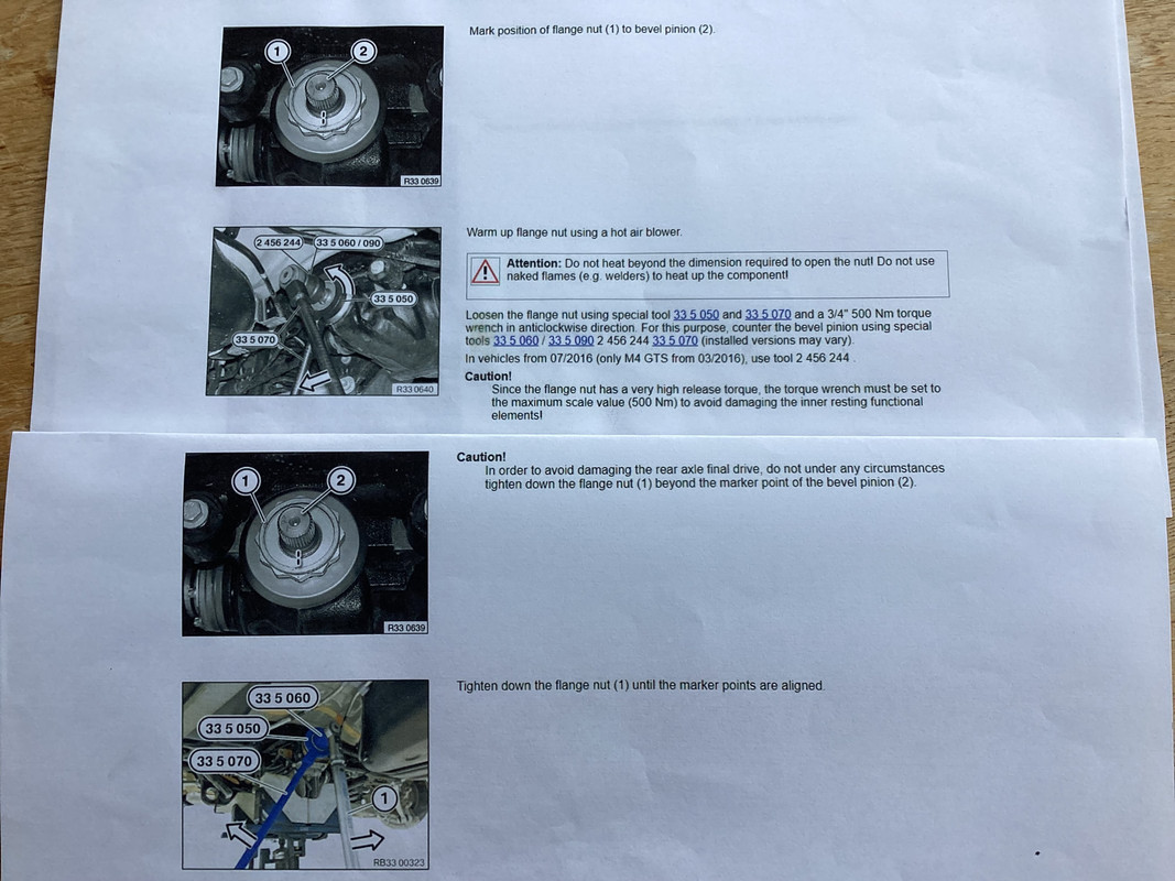
Hi Steve......did you mark the nut location before undoing it so that you can do it back up to exactly the same position...if not then think you need to take to a Diff specialist to have it stripped set up again... Steve
Hello Steve,
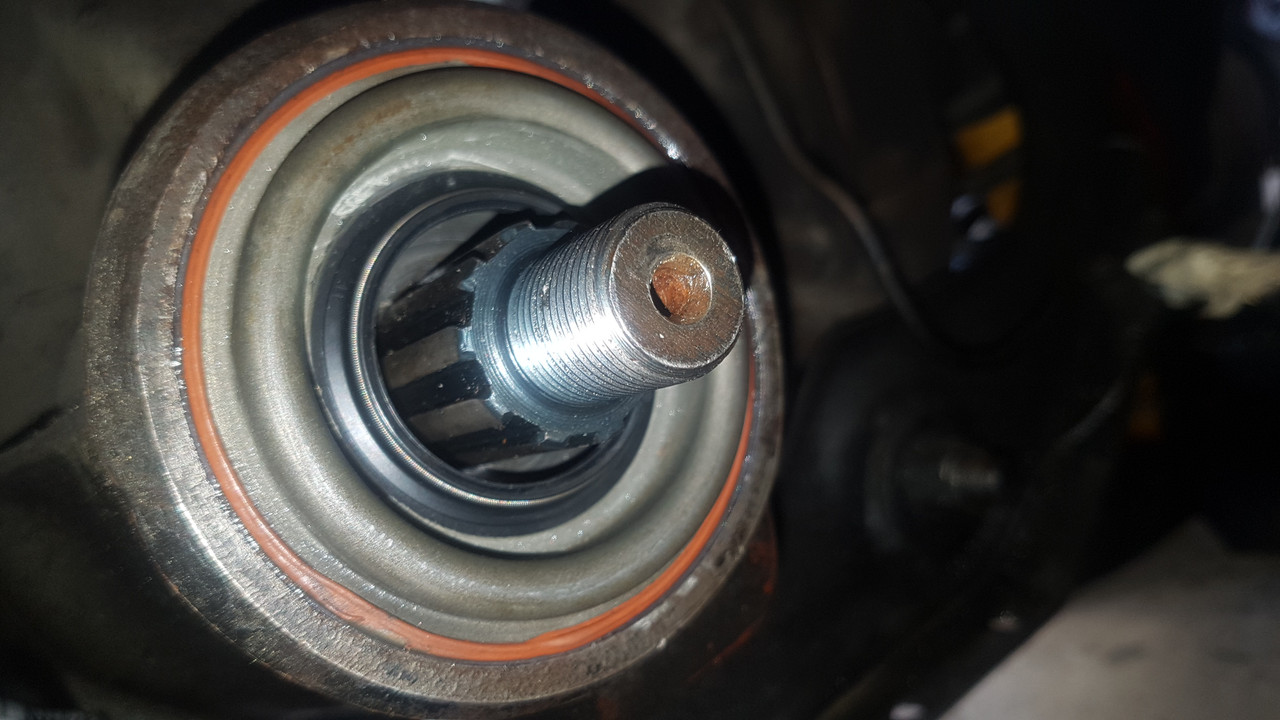
Except when the nut is not tightened to have either no end play, or bearing pre-load, removing and doing the Companion Flange Nut up to a different position has no effect whatsoever on the Crown Wheel and Pinion set-up, only the pre-load (or lack thereof) of the Pinion Shaft bearings. Pursuant to the instructions given in the Workshop Manual, if this nut is over torqued, or removed, the collapsible spacer that is positioned between the set of two taper roller bearings should be replaced with a new spacer and the nut tightened to the correct torqued.
Because this collapsible spacer is positioned between the two bearings, its effect is to keep the bearings apart. Accordingly, the logic is that this spacer must collapse just the right amount so that the bearing cones come into contact with their corresponding cups with the applied torque to the nut. Presumably, this occurs at a predetermined torque just shy of the specified torque and therefore, a pre-load of the bearing system will exist when the specified torque is reached. Once the cones are in intimate contact with their cups and the system starts to apply a pre-load, no further collapse of the spacer occurs (I've determined this by torquing the nut to varying torque beyond the 120 to 140lb/ft specified, up to 250lb/ft, recovering the spacer, measuring and comparing lengths. Accordingly, I see no validity in the Workshop Manual statement that "Should the nut be inadvertently over-tightened, the flange must be removed and a new collapsible spacer fitted. On no account must the nut be slackened off and re-torqued, as this will result in incorrect pre-loading of drive pinion bearings".
This system relies on so many ducks being inline:
1. just the right amount of preliminary crush of the supplied, new spacer
2. the exact same wall thickness of the tube used in the manufacture of the spacer as the original design.
3. the exact (within design tolerance) same length as the original design.
4. same material hardness as the original design
that, in my opinion, this system is profoundly flawed.
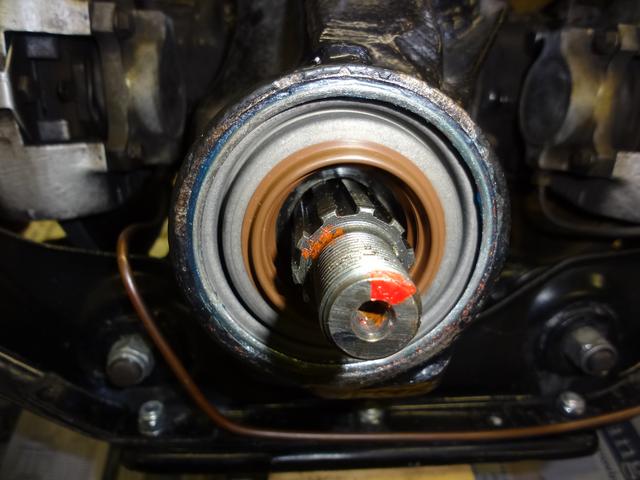
The system employed before the collapsible spacer was introduced, was the use of shims to set the pre-load on the bearings, with the final test being a specified torque needed to turn the pinion shaft (8lb/ft). For many years, I've mimicked the earlier system by using a non-collapsible spacer to replace the collapsible spacer.
I use a Master Spacer that is slightly longer than required. This results in measurable end float when the Companion Flange nut to tightened. Given the measured end float and the known length of the Master Spacer, the correct length spacer is easily calculated. The final test after the nut is torqued up is to check the torque required to rotate the pinion shaft.
I doubt when the collapsible spacer system was suggested that the words "here is a much better system we have developed" were used in a sentence, but more likely "we have developed this cheap and nasty, cost saving system".
Regards,
Bill