Hello,
I have a 4.2 serie 1 65, battery is not charging and the ignition light on the rev counter is not lighting before the engine starts. Before the full restoration it was charging well, I have a new wiring loop with autospark. After many research on the forum I have several questions :
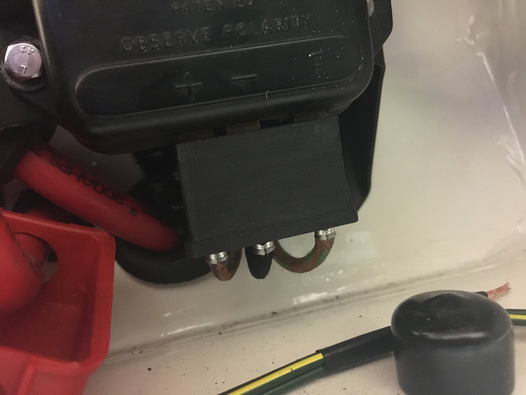
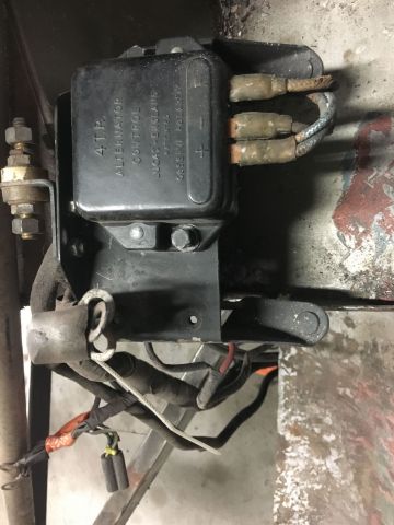
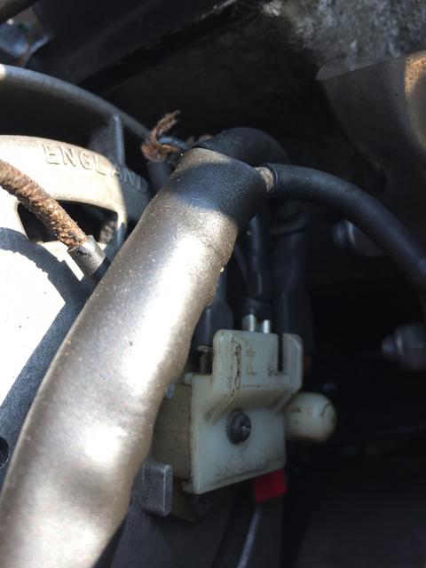
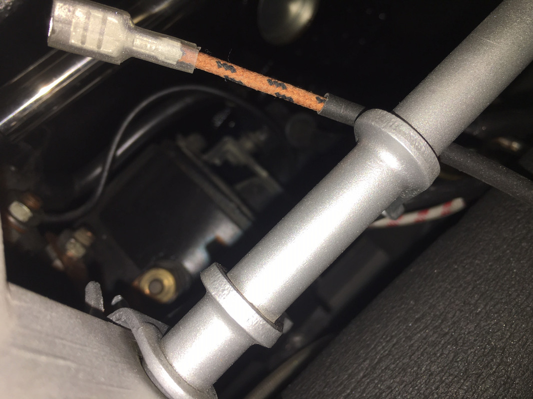
1°) Ignition light : Per this topic (viewtopic.php?f=4&t=6315&hilit=alternator&start=20) what is the correct answer ? I have 4TR regulator, the ignition light to the dashboard is a white +12V with a Brown/black wire. The same brown/black wire "exit out" just in front of the oil filter (picture below). Is there other ignition light wiring than using pressure swith ?
2°) 4TR regulator : how to test it ?
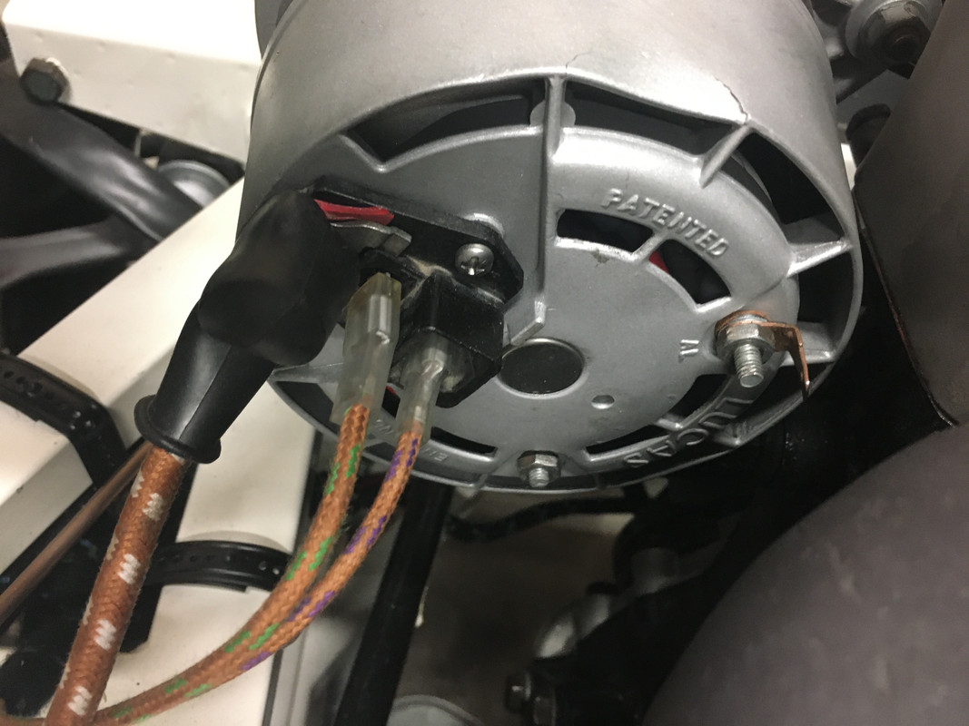
3°) alternator itself : this a standard 11C, is there a solution to test it while engine is running ?
Thanks for your help, I stucked for the moment with this issue ...
Electrical system not charging 65 S1 4.2
#1 Electrical system not charging 65 S1 4.2
Last edited by cooper66 on Sun Jan 05, 2020 6:26 pm, edited 3 times in total.
Pierre
Link: | |
BBcode: | |
HTML: | |
Hide post links |
#2 Re: alternator charging and ignition light S1 4.2
Pierre Wrote:
If your car uses an oil pressure switch (OPS) on RH side of engine Block, the same wire that runs to the OPS can be connected to a 3AW unit. A wire would then have to come from the alternator to the AL terminal on the 3AW.
The Alternator Loom that operates with a 3AW is a small, separate loom that enters the cabin at the LH side, near the LH bonnet lock assembly, Accordingly. if your wiring loom doesn't include this, it can be purchased separately and is not very expensive. If you go that way, you have a choice of the standard (rather fragile) 3AW unit, or a solid state device. I would opt for the solid state unit.
Regards,
Bill
Hello Pierre,Is there other ignition light wiring than using pressure swith ?
If your car uses an oil pressure switch (OPS) on RH side of engine Block, the same wire that runs to the OPS can be connected to a 3AW unit. A wire would then have to come from the alternator to the AL terminal on the 3AW.
The Alternator Loom that operates with a 3AW is a small, separate loom that enters the cabin at the LH side, near the LH bonnet lock assembly, Accordingly. if your wiring loom doesn't include this, it can be purchased separately and is not very expensive. If you go that way, you have a choice of the standard (rather fragile) 3AW unit, or a solid state device. I would opt for the solid state unit.
Regards,
Bill
Link: | |
BBcode: | |
HTML: | |
Hide post links |
#3 Re: alternator charging and ignition light S1 4.2
To test the alternator with the engine running, measure the voltage across the battery terminals. It should be around 14 volts.
Tom
1970 S2 FHC
1970 S2 FHC
Link: | |
BBcode: | |
HTML: | |
Hide post links |
#4 Re: alternator charging and ignition light S1 4.2
Hello, I know I have 12,5V this is why I know the alternator is not charging at all and I have several questions :
-How to test the alternator itself engine running ?
-How to test the regulator ? 4TR one on my car
-what else I'm missing on the system ?
-The ignition light has nothing to do with charging system if I'm right, so this is not the rootcause.
Thanks in advance
Pierre
Link: | |
BBcode: | |
HTML: | |
Hide post links |
#5 Re: alternator not charging S1 4.2
You’re correct, with this alternator setup, the warning light isn’t necessary for the system to charge.
I’d start by checking if the alternator relay is working. It’s located on the LHS mudshield, and disconnects the alternator from the battery when the ignition is off.
Which version of 4tr do you have? There’s versions with different numbers of terminals. To test, I find it easier to replace with a new one. They’re not expensive, and it’s worth having a spare in the car. If replacing it doesn’t fix things, then you know to investigate further.
If you want to investigate further on the alternator, I’d check the voltage at the main terminal and also check if the field terminal is being energised. There’s usually a detailed alternator test procedure in the workshop manual or in a Lucas manual.
Tom
1970 S2 FHC
1970 S2 FHC
Link: | |
BBcode: | |
HTML: | |
Hide post links |
#6 Re: alternator not charging S1 4.2
I don't have alternator relay on my car (65) I think it appeared on later cars (67/68).
To be honest I don't know which version I have, mine has 3 lugs/terminals (picture below)
And I have the following connections to the alternator. Alternator was rebuilt by professional this week and was not operative (new diode pack, new brush and new bearings
to be honest I'm lost everything is correct per the wiring loom diagram, but I must miss something for sure ...
Did I inverse the brown/green and brown/purple on the alternator ? the B+ (big brown/white) is correct, and the closest lug is normally the "F-" if I'm correct, then "F+" is the third one in brown/purple.
Thanks for your help I'm losing faith
Pierre
Link: | |
BBcode: | |
HTML: | |
Hide post links |
#7 Re: Electrical system not charging 65 S1 4.2
Unless your alternator has been modified with a trio of diodes, you will have a relay for the alternator. Without it, the alternator will drain the battery when the ignition is switched off.
You have a 3 pin regulator. Pull down the plug slightly to expose the terminals. With the car running, measure the voltage at the + terminal. This is the voltage the regulator “sees” to decide when the alternator should charge. It should be around 14v.
It looks like you have a wire missing on the alternator. The AL terminal should be connected. This circuit makes the warning light go out. The wiring to the alternator should have brown purple to field positive, and brown green to field negative. Field negative goes to the F terminal on the regulator, and field positive goes to the alternator relay. It should be labelled on the alternator terminals which is F+ and which is F-. On mine F- is closer to the B+ terminal, but the terminal block on my alternator is slightly different to yours.
Also, has your alternator been dropped? There’s a big dent in the end housing.
Tom
1970 S2 FHC
1970 S2 FHC
Link: | |
BBcode: | |
HTML: | |
Hide post links |