


Photo of a front suspension setting tool?
#1 Photo of a front suspension setting tool?
Does anyone have a clear photo of a front suspension setting tool, either in situ or on its own?
Phil
1962 FHC 885626
1962 FHC 885626
| Link: | |
| BBcode: | |
| HTML: | |
| Hide post links |

#2 Re: Photo of a front suspension setting tool?
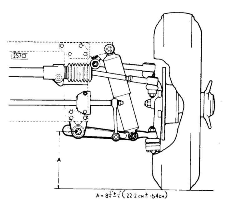
Hi Phil....drawings with dimensions are in the service manual..for both the ride height tool and castor tool. In situ and on their own....Steve
Steve
69 S2 2+2 (just sold) ..Realm C type replica, 1960 xk150fhc
69 S2 2+2 (just sold) ..Realm C type replica, 1960 xk150fhc
| Link: | |
| BBcode: | |
| HTML: | |
| Hide post links |
#3 Re: Photo of a front suspension setting tool?
Thanks Steve, I have that but was looking for a photo as well.
Phil
1962 FHC 885626
1962 FHC 885626
| Link: | |
| BBcode: | |
| HTML: | |
| Hide post links |
-
christopher storey
- Posts: 5698
- Joined: Sun Mar 09, 2008 3:07 pm
- Location: cheshire , england

#4 Re: Photo of a front suspension setting tool?
Phil : you really don't need a photo, or for that matter the proper tool . Just get a bit a 2" X 1" ( or better still 2 X 1/2 ) and mark off the prescribed distances and drill it accurately to suit the bolts, the size of which I have forgotten . Voila, your setting tool !
| Link: | |
| BBcode: | |
| HTML: | |
| Hide post links |

#5 Re: Photo of a front suspension setting tool?
Richard
Previous owner and restorer of a S1 3.8 FHC Opalescent Golden Sand with Tan Trim 889504 (now sold and headed for Athens)


Previous owner and restorer of a S1 3.8 FHC Opalescent Golden Sand with Tan Trim 889504 (now sold and headed for Athens)
| Link: | |
| BBcode: | |
| HTML: | |
| Hide post links |
#6 Re: Photo of a front suspension setting tool?
Thanks chaps
Phil
1962 FHC 885626
1962 FHC 885626
| Link: | |
| BBcode: | |
| HTML: | |
| Hide post links |

#7 Re: Photo of a front suspension setting tool?
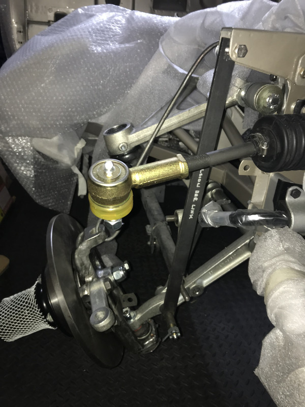
The challenge of using the drop-link measurement guide is that it assumes the torsion bars are at optimum factory strength whereas used torsion bars will vary in tensile strength (particularly on LHD drive cars where the nearside of the car has borne both the driver's weight as well as the petrol tank for the lifespan of the car). New torsion bars are "uprated" by virtue of being slightly thicker, are therefore stiffer and do not twist as much under load as factory originals.
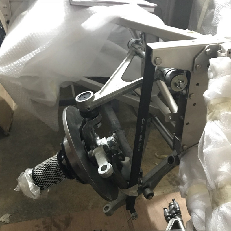
On our car, we have a Rob Beere adjustable reaction plate to adjust the torsion bars in-situ and we then use the following homemade device to measure the gap from the ground up to the suspension measurement point as shown in the Jaguar Service Manual.
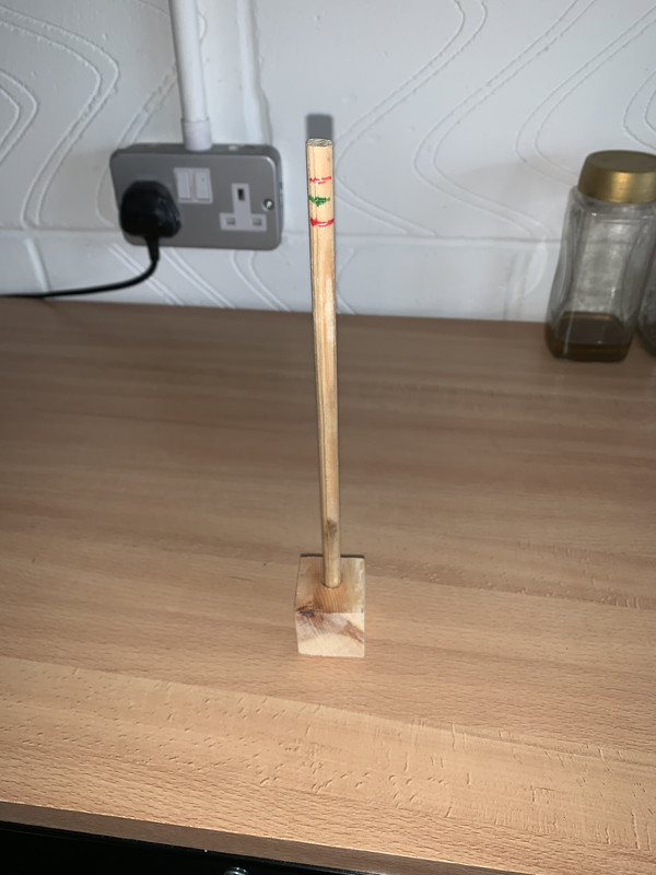
The green line represents the factory recommended height from the ground to the suspension joint and the red line represents the 1/4 inch factory tolerance either side of that. By simply standing the tool under the car you can see whether the ride height is correct/within tolderance on each side and then adjust the reaction plate accordingly to either tension up or slacken off the torsion bar on each side.
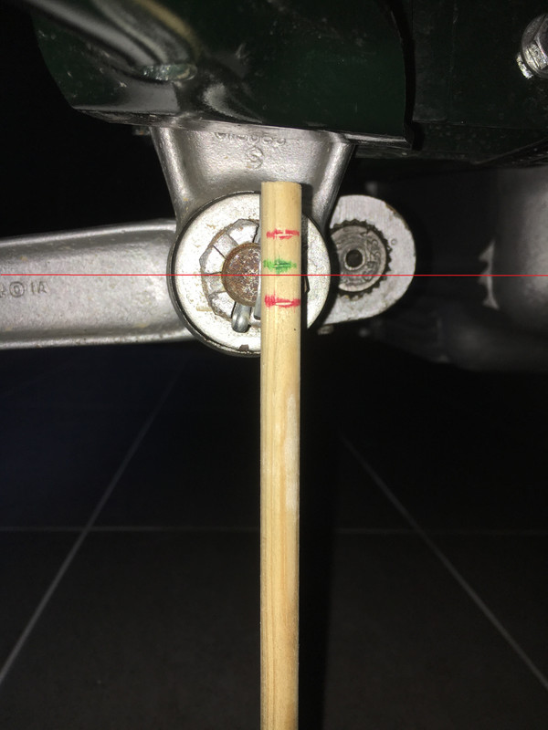
NB by using the factory ride height recommendations, this assumes you are using the correct tyres with the correct height sidewalls and tyre pressures. If you are using lower profile tyres, an appropriate adjustment would need to be made to compensate for this.
The advantage of this approach is that this takes into account the type/age of torsion bar you are using since it only looks at the end result (i.e. the ride height).
On our car, we have a Rob Beere adjustable reaction plate to adjust the torsion bars in-situ and we then use the following homemade device to measure the gap from the ground up to the suspension measurement point as shown in the Jaguar Service Manual.
The green line represents the factory recommended height from the ground to the suspension joint and the red line represents the 1/4 inch factory tolerance either side of that. By simply standing the tool under the car you can see whether the ride height is correct/within tolderance on each side and then adjust the reaction plate accordingly to either tension up or slacken off the torsion bar on each side.
NB by using the factory ride height recommendations, this assumes you are using the correct tyres with the correct height sidewalls and tyre pressures. If you are using lower profile tyres, an appropriate adjustment would need to be made to compensate for this.
The advantage of this approach is that this takes into account the type/age of torsion bar you are using since it only looks at the end result (i.e. the ride height).
Phil
1964 S1 3.8 OTS
1964 S1 3.8 OTS
| Link: | |
| BBcode: | |
| HTML: | |
| Hide post links |
#8 Re: Photo of a front suspension setting tool?
Hello, can anyone tell me the dimension (between hole centres) of the tool shown in#5 please?
Recognising the valid points made about torsion bars.
Thanks in advance
Clive
Recognising the valid points made about torsion bars.
Thanks in advance
Clive
Clive
| Link: | |
| BBcode: | |
| HTML: | |
| Hide post links |
#9 Re: Photo of a front suspension setting tool?
Depends what model and spec car you have......dimensions for all are in the service manual....Steve
Steve
69 S2 2+2 (just sold) ..Realm C type replica, 1960 xk150fhc
69 S2 2+2 (just sold) ..Realm C type replica, 1960 xk150fhc
| Link: | |
| BBcode: | |
| HTML: | |
| Hide post links |
#10 Re: Photo of a front suspension setting tool?
I found the answer to my own question - the distance is 343 mm for the "mid laden" condition. I believe that's for early cars but it was enough detail for my purpose.
Cheers
Cheers
Clive
| Link: | |
| BBcode: | |
| HTML: | |
| Hide post links |
#11 Re: Photo of a front suspension setting tool?
No......that measurement is for the castor angle setting link....not for ride hight setting link....Steve
Steve
69 S2 2+2 (just sold) ..Realm C type replica, 1960 xk150fhc
69 S2 2+2 (just sold) ..Realm C type replica, 1960 xk150fhc
| Link: | |
| BBcode: | |
| HTML: | |
| Hide post links |