


I'm going to make a little gadget to go behind the dash which will make the gauge read correctly. It'll be user adjustable and will mean you don't need to buy a new sender when yours "goes off".
Let me know (on this thread - not via PM as my mailbox is always full) if you are interested.
kind regards
Marek
oil pressure sender calibration widget

#2 Re: oil pressure sender calibration widget
Great idea Marek.......im sure it will be usefull to many........Steve
Steve
69 S2 2+2 (just sold) ..Realm C type replica, 1960 xk150fhc
69 S2 2+2 (just sold) ..Realm C type replica, 1960 xk150fhc
| Link: | |
| BBcode: | |
| HTML: | |
| Hide post links |


#3 Re: oil pressure sender calibration widget
Regards,
ColinL
'72 OTS manual V12
ColinL
'72 OTS manual V12
| Link: | |
| BBcode: | |
| HTML: | |
| Hide post links |
-
Gfhug
- Posts: 3317
- Joined: Thu Jun 19, 2014 3:08 pm
- Location: Near Andover, Hampshire,in D.O. Blighty

#4 Re: oil pressure sender calibration widget
That’s a fine idea Marek.
Geoff
Geoff
S2 FHC Light Blue
S2 OTS LHD - RHD full restoration
S2 OTS LHD - RHD full restoration
| Link: | |
| BBcode: | |
| HTML: | |
| Hide post links |

#5 Re: oil pressure sender calibration widget
+1 
Yves, happy XKE 63 fhc , w113 280sl owner
Looking for a OTS 4.2 serie 1....! and now have found a fhc xk 140
Looking for a OTS 4.2 serie 1....!
| Link: | |
| BBcode: | |
| HTML: | |
| Hide post links |
#6 Re: oil pressure sender calibration widget
+2
Mike - 1962 OTS 878380, 1965 Honda S600, 2001 Honda S2000
| Link: | |
| BBcode: | |
| HTML: | |
| Hide post links |
-
Geoff Allam
- Posts: 201
- Joined: Sat Mar 31, 2018 12:55 am

#7 Re: oil pressure sender calibration widget

Geoff Allam
67 series1 ots under restoration
67 series1 ots under restoration
| Link: | |
| BBcode: | |
| HTML: | |
| Hide post links |
#8 Re: oil pressure sender calibration widget
How does it work?
Is it accurate from 0 to maximum?
At the end of the day an accurate indication of low pressure is the most important piece of information the oil pressure gauge provides. Will this adjustment guarantee this?
Is it accurate from 0 to maximum?
At the end of the day an accurate indication of low pressure is the most important piece of information the oil pressure gauge provides. Will this adjustment guarantee this?
Andrew.
881824, 1E21538. 889457. 1961 4.3l Mk2. 1975 XJS. 1962 MGB
http://www.projectetype.com/index.php/the-blog.html
Adelaide, Australia
881824, 1E21538. 889457. 1961 4.3l Mk2. 1975 XJS. 1962 MGB
http://www.projectetype.com/index.php/the-blog.html
Adelaide, Australia
| Link: | |
| BBcode: | |
| HTML: | |
| Hide post links |
-
 ralphr1780
- Posts: 1067
- Joined: Wed Apr 11, 2012 4:29 pm

#9 Re: oil pressure sender calibration widget
+2 
Ralph
'69 OTS + '62 OTS - Belgium
'69 OTS + '62 OTS - Belgium
| Link: | |
| BBcode: | |
| HTML: | |
| Hide post links |
#10 Re: oil pressure sender calibration widget
Dear Andrew,
It'll scale the output of the "lazy" oil sender you currently have and you'll be able to calibrate it with a bicycle pump or against a mechanical gauge.
kind regards
Marek
It'll scale the output of the "lazy" oil sender you currently have and you'll be able to calibrate it with a bicycle pump or against a mechanical gauge.
kind regards
Marek
| Link: | |
| BBcode: | |
| HTML: | |
| Hide post links |
#11 Re: oil pressure sender calibration widget
Hi Marek...im not sure what your saying here........will there just be one calibration pressure that you then set to the guage reading.....or will it be a more complex widget that enables the guage to give correct readings from 0-60... thanks....Steve
Steve
69 S2 2+2 (just sold) ..Realm C type replica, 1960 xk150fhc
69 S2 2+2 (just sold) ..Realm C type replica, 1960 xk150fhc
| Link: | |
| BBcode: | |
| HTML: | |
| Hide post links |
#12 Re: oil pressure sender calibration widget
Your current sender works just like the 10v voltage regulator behind the dash. There is a bimetallic strip mechanism inside which is constantly turning on and off, so this controls the current going through the gauge and therefore where the slow moving gauge needle settles at. On top of that, the sender's bimetallic strip distance between it's OFF and ON states is controlled by a plug which is pushed up by oil pressure. This alters the ON to OFF ratio of the sender in proportion to oil pressure. That affects the gauge needle. Sadly, the numbers on the gauge don't correspond to the actual pressure.
My proposal is to not use the sender to drive the gauge directly, but use it to drive a circuit whose output can be set in proportion to the sender. It's up to you to dial in what you want that multiplication factor to be and you'd do it with a screwdriver. The sender has a standard BSP thread, so you can attach it to an air compressor and read what the car's gauge says. Then you can alter the calibration until the car's gauge matches that on the compressor.
The sender's efficacy and accuracy are not affected whatsoever.
If you want to have a play and see whether your current sender is accurate at different pressures, then you can do that now with a compressor anyway. Just remember the gauge needle moves slowly and the sender needs to be grounded.
kind regards
Marek
| Link: | |
| BBcode: | |
| HTML: | |
| Hide post links |
#13 Re: oil pressure sender calibration widget
OK. Put me down for one!
Andrew.
881824, 1E21538. 889457. 1961 4.3l Mk2. 1975 XJS. 1962 MGB
http://www.projectetype.com/index.php/the-blog.html
Adelaide, Australia
881824, 1E21538. 889457. 1961 4.3l Mk2. 1975 XJS. 1962 MGB
http://www.projectetype.com/index.php/the-blog.html
Adelaide, Australia
| Link: | |
| BBcode: | |
| HTML: | |
| Hide post links |
#14 Re: oil pressure sender calibration widget
I've been looking at this again today and I think I can simply recalibrate the curve and not just scale the sender output. This means you can simply dial in the multiplication factor (i.e. the gradient of the curve) at various points on the oil pressure versus voltage graph, boosting it or dropping it down as required.
Put another way, any oil sender can be made to read correctly. Even non standard gauges can be accommodated.
I'd probably give you some set calibration points like 60psi, 40psi, 20psi plus a general multiplier up to 80psi. Given the gauge is quite small, I think fitting a curve at four defined points is probably enough.
It'd be helpful to have a few example table readouts of "voltage on gauge" versus "indicated psi" versus "actual psi".
kind regards
Marek
| Link: | |
| BBcode: | |
| HTML: | |
| Hide post links |
#15 Re: oil pressure sender calibration widget
Hi Marek.
Imo it would be ideal if one of the calibration points was 10 psi, some of the (new) senders I have purchased were wonky/non existent below 20 psi and below 10 psi would be engine off for me ...
I am imagining it would need to be connected as follows (S3 diag) ????
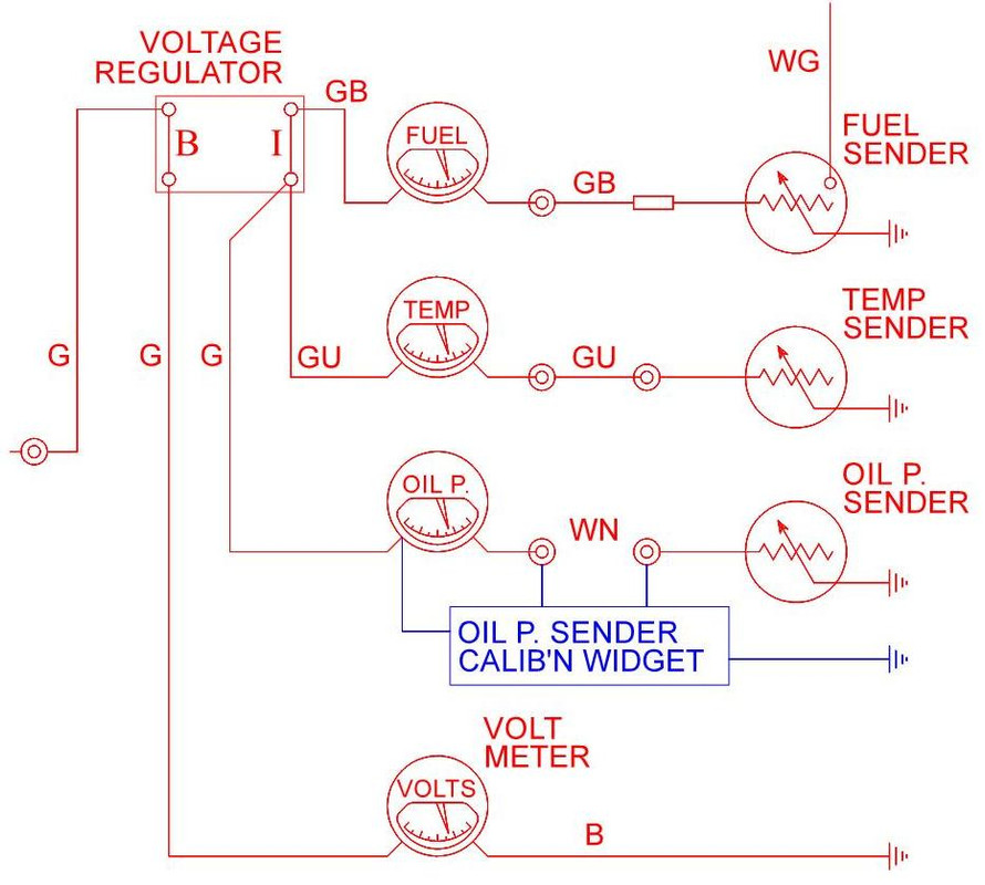
Regulated pwr supply so resistive (PTS) senders have consistent output.
Its own earth so that gauge display can use the widget output.
Within the capacity of the voltage regulator so that fuel and temp gauges are not effected?
Imo it would be ideal if one of the calibration points was 10 psi, some of the (new) senders I have purchased were wonky/non existent below 20 psi and below 10 psi would be engine off for me ...
I am imagining it would need to be connected as follows (S3 diag) ????
Regulated pwr supply so resistive (PTS) senders have consistent output.
Its own earth so that gauge display can use the widget output.
Within the capacity of the voltage regulator so that fuel and temp gauges are not effected?
Regards,
ColinL
'72 OTS manual V12
ColinL
'72 OTS manual V12
| Link: | |
| BBcode: | |
| HTML: | |
| Hide post links |
#16 Re: oil pressure sender calibration widget
Power will come directly from the unregulated supply. The old 10v regulators are nothing but on:off switches so are unsuitable sources of power for anything but a bimetallic strip gauge, so the widget and gauge will have their own supply independent of the old 10v "regulator".
The calibration points are where are where adjustments cut in or cut out and the adjustment is proportional to how far away from the calibration point the gauge is reading.
For example, with a single calibration point at 40psi, it'd give you no adjustment at 40psi, but you'd get a big adjustment at either (or both - your choice!) 0psi or 80psi, so a previously straight line curve response would either either dip in the middle or be bowed upwards in the middle at 40psi
The adjustments would be as follows:-
1/ basic height of the PSI vs voltage curve
2/ basic multiplication factor for whole curve
plus
3/ adjustment of curve gradient for psi vs voltage curve for all values greater than "x" PSI in proportion to how far away (i.e. above) "x" PSI you are (where "x" is 60, 40, 20ish PSI)
4/ adjustment of curve gradient for psi vs voltage curve for all values greater than "x" PSI in proportion to how far away (i.e. below) "x" PSI you are (where "x" is 60, 40, 20ish PSI)
The "3/" adjustments make the overall curve look flatter at low PSI and point upward more at high PSI
The "4/" adjustments make the curve point downward at lower PSI and flatten off at high PSI
I expect most people want a little bit of "2/" so the high end reads correctly plus a lot of "3/" at the calibration points. That modestly pulls up the whole curve but keeps boosting the low PSI end proportionately more the lower the PSI reading from the gauge.
Looking at Philip Lochner's numbers from viewtopic.php?f=6&t=13176&hilit=oil+sender then a 0% basic ("1/") adjustment of the whole curve a plus 20% "/3" adjustment to all values lower than 60psi, a further 20% to all values lower 40psi and 40% adjustment to all values lower than 20psi would make the gauge read correctly.
kind regards
Marek
| Link: | |
| BBcode: | |
| HTML: | |
| Hide post links |

#17 Re: oil pressure sender calibration widget

Malcolm
I only fit in a 2+2, so got one!
1969 Series 2 2+2
2009 Jaguar XF-S
2015 F Type V6 S
I only fit in a 2+2, so got one!
1969 Series 2 2+2
2009 Jaguar XF-S
2015 F Type V6 S
| Link: | |
| BBcode: | |
| HTML: | |
| Hide post links |
-
ralphr1780
- Posts: 1067
- Joined: Wed Apr 11, 2012 4:29 pm
#18 Re: oil pressure sender calibration widget
I have upgraded to electronic 10v regulator long time ago and the gauges reading became much more consistent.MarekH wrote: ↑Tue Mar 08, 2022 10:07 amPower will come directly from the unregulated supply. The old 10v regulators are nothing but on:off switches so are unsuitable sources of power for anything but a bimetallic strip gauge, so the widget and gauge will have their own supply independent of the old 10v "regulator".
Ralph
'69 OTS + '62 OTS - Belgium
'69 OTS + '62 OTS - Belgium
| Link: | |
| BBcode: | |
| HTML: | |
| Hide post links |
#19 Re: oil pressure sender calibration widget
Dear Malcolm (and others),
please connect up an air compressor to your sender (they are both 1/4"BSP threads) and fill in the following table values for x and a-j.
supply voltage x volts
voltage
pressure across
PSI gauge
0 a
10 b
20 c
30 d
40 e
50 f
60 g
70 h
80 I
90 j
The body of the sender needs to remain earthed for a-j.
The supply voltage is that between the gauge's green wire and earth.
I'll then post a table of how "off" your sender is and how to correct it.
kind regards
Marek
| Link: | |
| BBcode: | |
| HTML: | |
| Hide post links |
-
 chrisallen01
- Posts: 59
- Joined: Thu Mar 06, 2014 9:01 pm
- Location: United Kingdom
#20 Re: oil pressure sender calibration widget
Am I missing something here? I simply replaced the dodgy sender unit and electric gauge with a very similar mechanical gauge only difference is the gauge scale is 0 - 100 psi and shows 50psi at the 6 o'clock position.
Chris
69 S2 FHC OEW P1R27068
Oxford UK
69 S2 FHC OEW P1R27068
Oxford UK
| Link: | |
| BBcode: | |
| HTML: | |
| Hide post links |