Is It 'Cos I Is Thick ???? Trakrite Camber Caster Gauge ....

Technical advice Q&A
User avatar

Topic author
rfs1957
Posts: 1326
Joined: Sat Jan 15, 2011 2:52 pm
Location: Languedoc - France
France

#1 Is It 'Cos I Is Thick ???? Trakrite Camber Caster Gauge ....

Post by rfs1957 » Thu Dec 11, 2014 1:26 pm

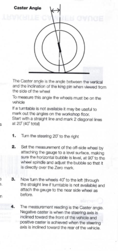
Wasn't actually using this on the Jag but on the Mini, tried to measure the Caster. Read the instructions left to right, right to left, then front to back, to no avail - I Is Indeed Thick.

Image

Image

But maybe not that thick since I ventured that "the instructions for Caster Angle are so awful and incorrect as to be risible ; the caster angle is specific to each king-pin pair (left or right) and the notion that you measure both at the same time as per the instructions - did anybody ever actually read what was printed ? - makes the tool worse than useless."

The manufacturer replied that "interestingly in the 5000 units sold in the last 2 years you are the first to report the error" and "I will do my best to provide you with some useable instruction. This will take some time as we will need to check the instructions for accuracy."

Anyone else come across this ? And how does a 40° swing in the steering enable one to deduce a camber angle - beats my geometry. Bear in mind that the same read-off on the bubble calibration is used to give camber angles too.
Last edited by rfs1957 on Thu May 04, 2017 1:08 pm, edited 2 times in total.
Rory
3.8 OTS S1 Opalescent Silver Grey - built May 28th 1962

Link:
BBcode:
HTML:
Hide post links
Show post links


david muir
Posts: 244
Joined: Mon Feb 20, 2012 9:24 pm
Location: Perthshire
Scotland

#2 Caster etc

Post by david muir » Thu Dec 11, 2014 2:58 pm

Yes Rory,
I have had difficulty understanding it all!. Think I found some other instructions on the 'net but can't remember now! . One would think, for the price of the tool, that there would be clear and decent instructions with , perhaps, a couple of photographs!!
D
1964 3.8 FHC

Link:
BBcode:
HTML:
Hide post links
Show post links


david muir
Posts: 244
Joined: Mon Feb 20, 2012 9:24 pm
Location: Perthshire
Scotland

#3 Caster etc

Post by david muir » Thu Dec 11, 2014 3:02 pm

https://www.pegasusautoracing.com/pdfs/ ... IGauge.pdf
Think these are the instructions I previously found![maybe a different gauge from yours Rory!]

D
1964 3.8 FHC

Link:
BBcode:
HTML:
Hide post links
Show post links


jag68
Posts: 181
Joined: Wed Mar 20, 2013 6:24 pm
Location: Victoria BC Canada
Canada

#4

Post by jag68 » Thu Dec 11, 2014 6:37 pm

Rory
If you do a thought experiment and imagine that the upright were mounted horizontally instead of nearly vertical you can easily see that steering movements would not actually turn the wheel but would induce a 100% camber change in the wheel. In real life the upright being only slightly off vertical induces a smaller amount of camber change when the steering gear turns the wheel. The steering turns the wheel and changes camber as it does so. Your gauge is actually measuring this camber change, over a limited range of steering induced movement - 40 degrees in fact. You "zero" the gauge when the wheel is turned in 20 degrees and read it when it's turned out 20 degrees, so you don't have to do any complex calculations required if not "zeroed". So why is 40 degrees of steering movement used? It appears to be nothing more than the manufacturer saying: "At 40 degrees of wheel movement caster should be X degrees of camber movement", instead of saying: At 80 degrees of wheel movement caster should be 2X", or at 20 degrees = 1/2X, with X being the recommended caster. Everybody in the business seemingly understands that the measurement is made at 40 degrees of wheel movement. Does this actually mean that the upright is X degrees off vertical - I don't know, but I suspect it's close but not exact?
1967 E Type coupe
1968 E Type OTS
2007 XKR

Link:
BBcode:
HTML:
Hide post links
Show post links


steve3.8
Posts: 459
Joined: Sun Mar 22, 2009 9:12 pm
Location: nottinghamshire,uk
Great Britain

#5 Re: Is It 'Cos I Is Thick ???? Trakrite Camber Caster Gauge

Post by steve3.8 » Thu Dec 11, 2014 7:13 pm

Rory ,

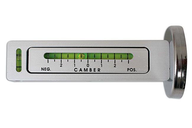
I also bought one of these gauges and yes the instructions are a wind up . basically to measure camber set the gauge to zero in conjunction with a spirit level then stick the gauge on a piece of flat bar that will rest on the wheel rim , level the bubble in the horizontal and then read the camber angle , obviously with correct tyre pressures , wheels pointing straight forward and the car on a level surface .


Anyone else come across this ? And how does a 40? swing in the steering enable one to deduce a camber angle - beats my geometry. Bear in mind that the same read-off on the bubble calibration is used to give camber angles too.[/quote]

To measure castor turn steering on way 20? from straight zero both bubbles , then turn steering 40? opposite way , then read the angle .

Regards Steve
Steve3.8

64 3.8 fhc, 67 4.2 fhc

Link:
BBcode:
HTML:
Hide post links
Show post links

User avatar

Topic author
rfs1957
Posts: 1326
Joined: Sat Jan 15, 2011 2:52 pm
Location: Languedoc - France
France

#6

Post by rfs1957 » Thu Dec 11, 2014 9:29 pm

Sorry, I dońt buy some of this. Castor is an angle, a fixed one, and not one that is specified or defined according to a given range of rotation of the hub.
If the Gunson tool uses some kind of TOA. SOH CAH trig reasoning to induce from a plus 20 minus 20 swing what the caster is then I'd be intruiged to read about it. I think it speaks volumes about the home mechanic market that 'nobody has ever complained before', and explains why I missed out on several Ebay sales for the proper Dunlop kit - others have come to the conclusion that you get what you pay for. Having said that, the CAMBER function appears satisfactory.
Rory
3.8 OTS S1 Opalescent Silver Grey - built May 28th 1962

Link:
BBcode:
HTML:
Hide post links
Show post links

User avatar

PeterCrespin
Posts: 4561
Joined: Fri Mar 05, 2010 8:22 pm
Location: Gaithersburg, Maryland.
Contact:
United States of America

#7

Post by PeterCrespin » Thu Dec 11, 2014 10:35 pm

I used mine by attaching it to the discs. It was 4 years ago but don't recall any issues. I probably used a builder's level at some point along and across the frames to make sure I had the car level front to back and side to side (no wheels or bonnet attached during build up.
1E75339 UberLynx D-Type; 1R27190 70 FHC; 1E78478; 2001 Vanden Plas

Link:
BBcode:
HTML:
Hide post links
Show post links


jag68
Posts: 181
Joined: Wed Mar 20, 2013 6:24 pm
Location: Victoria BC Canada
Canada

#8

Post by jag68 » Fri Dec 12, 2014 9:24 am

Rory
You're missing the bigger picture here. Castor is a fixed angle but that's not what we're talking about - we're simply talking about how you measure that fixed angle. Gauges that measure camber change and relate it to the castor angle have been around for years, and work. I use the Longacre gauge part no 78260 with a magnetic base that attaches itself to the end of the knock off hub - been using it for a long time. I perhaps phrased my explanation in an unclear fashion. When the wheel assembly is turned by the steering gear and rotates on the axis between upper and lower ball joints that are not directly in line to each other (the definition of castor angle) that is, the axis is not on a line 90 degrees from the ground, that rotation will induce a camber change in the wheel. (This is easily imagined if you think of the ball joints being horizontal. Rotating the wheel on horizontal ball joints induces the ultimate camber change) The greater the inclination of the ball joints from the perpendicular position the greater is the castor and the greater is the induced camber change - from zero (wheel perfectly upright) if the joints are perpendicular to each other to 100% camber if if the joints are horizontal - remember in this thought experiment the wheel is not now rotating vertically but is rotating around a horizontal axis - the maximum (90 degree) castor angle.). Here's the kicker - it has to be obvious that if you are measuring the camber change caused by a non perpendicular axis as you rotate the wheel around that axis you must therefore be measuring the angle of that axis from perpendicular which is, in other words, the inclination of the upper ball joint to the lower ball joint - that fixed inclination being the castor angle.

It's hard to get your head around this - but trust me - that's how these gauges work.
1967 E Type coupe
1968 E Type OTS
2007 XKR

Link:
BBcode:
HTML:
Hide post links
Show post links

User avatar

PeterCrespin
Posts: 4561
Joined: Fri Mar 05, 2010 8:22 pm
Location: Gaithersburg, Maryland.
Contact:
United States of America

#9

Post by PeterCrespin » Fri Dec 12, 2014 12:36 pm

What's your name jag68? Thanks for taking the time to write down the explanation.

Rory has a slight point about the instructions not being super-wonderful but one doesn't expect lots of interesting explanations, just ABC on how to use the tool to get the desired result, which is what Trackrite provide. Plus if you start from a misapprehension even perfect instructions and background info might not 'click'. It will be interesting to see if/what they write back or if/how they tweak their instructions. My bet is they do nothing substantive since what they provide is at least adequate and there's an argument that says keeping it basic and simple causes fewest problems.

I think the equal angles either side of centre instruction is the clue that what the gauge is measuring is not sweep of the wheel per se but the angle of the pivot line from vertical, AKA castor, as you say.

Rory is a motorcyclist and will know that as you put a bike up on the centre stand the steering flops more heavily side to side if you sit on the back of a dual seat to compress the rear suspension and increase the castor angle. Since camber is always zero on a bike he may be getting blind-sided by the apparent 'variation' he sees as the E-type's steering turns.

Pete
1E75339 UberLynx D-Type; 1R27190 70 FHC; 1E78478; 2001 Vanden Plas

Link:
BBcode:
HTML:
Hide post links
Show post links


jag68
Posts: 181
Joined: Wed Mar 20, 2013 6:24 pm
Location: Victoria BC Canada
Canada

#10

Post by jag68 » Fri Dec 12, 2014 10:07 pm

Thanks Peter
These gauges as built can only MEASURE camber, but they can, in effect CALCULATE castor from the change in camber exhibited over a 40 degree sweep of the wheel assembly. Why 40 degrees - I believe that at 40 degrees the change in camber induced by the laid back axis between the ball joints equals the castor angle. More than 40 degrees and the change is greater than the castor - less than 40 it is less than the actual value. No doubt somebody - a math expert -not me - could provide the calculations necessary to show how the relationship works - all I know is follow the instructions and the gauge being programmed appropriately (a dumb program allbeit) does the "calculation" for you.

The instructions Rory got miss or better, inadequately explain, the first step. After you first attach the gauge to the off side wheel and zero the castor bubble in the vial, and then turn the steering back 40 degrees you read the castor ON THAT SIDE, you don't first move the gauge over to the other side. You then repeat the process on the nearside wheel reading the gauge while mounted on that side after turning the steering wheel back the 40 degrees. Just to be precise the castor is read twice - once per side. Castor can, and probably does, differ slightly from side to side.

As I mentioned the workings of this instrument are not intuitive - took me a few years before I realized what was going on. The Longacre gauge makes it a bit simpler as it has a machined surface on it that indicates 20 degrees either side of the center that you visually line up with the side of the car. Impossible to explain without a demonstration.

Terry Sturgeon
1967 E Type coupe
1968 E Type OTS
2007 XKR

Link:
BBcode:
HTML:
Hide post links
Show post links

User avatar

PeterCrespin
Posts: 4561
Joined: Fri Mar 05, 2010 8:22 pm
Location: Gaithersburg, Maryland.
Contact:
United States of America

#11

Post by PeterCrespin » Sat Dec 13, 2014 12:12 am

jag68 wrote:Thanks Peter
Why 40 degrees - I believe that at 40 degrees the change in camber induced by the laid back axis between the ball joints equals the castor angle. More than 40 degrees and the change is greater than the castor - less than 40 it is less than the actual value. No doubt somebody - a math expert -not me - could provide the calculations necessary to show how the relationship works - all I know is follow the instructions and the gauge being programmed appropriately (a dumb program allbeit) does the "calculation" for you.
Terry Sturgeon
Thanks Terry. You could be right (we probably have geometry/math experts here somewhere) but being a simpleton I assumed the reasons for selecting 20 degrees were much more basic. I wondered at the time why 20 but assumed, perhaps mistakenly, that:

a) 20 degrees suits the maximum number of cars. Too small an angle might be prone to a higher percentage error for each degree incorrectly measured. 30 degrees would be better than 20 in that respect but 60 degree total is more turn than some cars can deliver, especially race cars with wide rims and lock stops. The gauge is probably used by sports car people more than others and on the Goldilocks principle 20x2 is probably near-universally deliverable.

b) 20 degrees suits the gauge scale as made. As you indicated, the amount of flip-flop that the gauge reads changes by castor value. Therefore a longer/dearer/more fragile bubble gauge would be needed for reading greater deflections from the vertical due to greater included turn angle? The tool dimensions are matched to the required 20 each way deflection.

I think the pukka Dunlop-style tools are better or even the fancier Gunson gauge than the simple one I've got, but the Dunlop gauges are bulky/expensive and at the end of the day absolute accuracy is less important than consistency and repeatability, since most suspension settings are ultimately a question of 'feel' and compromise anyway.

Pete
1E75339 UberLynx D-Type; 1R27190 70 FHC; 1E78478; 2001 Vanden Plas

Link:
BBcode:
HTML:
Hide post links
Show post links


jag68
Posts: 181
Joined: Wed Mar 20, 2013 6:24 pm
Location: Victoria BC Canada
Canada

#12

Post by jag68 » Sat Dec 13, 2014 6:50 am

I've tried to find out why it's 20/20 or a total of 40 degrees without success. If the stub axle was 90 degrees to the ball joint to ball joint axis then turning the wheel assembly 90 degrees on that axis (in other words the hub would face straight back, the brake rotor would be 90 degrees to straight ahead, and would be parallel to the axis) the camber of the wheel would be exactly what the castor angle is - so why don't we turn the wheel 45/45 for a total of 90 degrees from straight ahead when using the gauge? (The stub axle on a E Type is actually not 90 degrees to the axis - look at the diagram of it in the manual, but regardless the angle of the rotor/wheel is always the same RELATIVE TO THE AXIS it rotates around.) Well firstly you can't physically turn the wheels through 90 degrees with the steering - that much movement is not possible, accordingly a gauge that required such movement would be useless. So I thought while writing this that I should have a look at the actual gauge. Bingo - the graduations on the castor scale are approximately one half as wide as on the camber scale running beside it. In other words when the gauge measures one degree of camber change it registers approximately 2 degrees of castor change. You don't need to rotate the wheel assembly 90 degrees, and if you did the castor registered by the gauge would be twice that of the actual castor. In brief the bubble in the castor gauge didn't move twice as far it just covered two times the scale of degrees marked beside it. The size of the scale on the castor vial in the tool must be 40/90th's of the camber scale. (No I'm not getting out the calipers to actually measure it.) Well firstly you learn something new everyday, and secondly this is my last word on this topic - I hope!

Terry Sturgeon
1967 E Type coupe
1968 E Type OTS
2007 XKR

Link:
BBcode:
HTML:
Hide post links
Show post links


Geoff Green
Posts: 141
Joined: Tue Apr 22, 2014 3:13 am
United States of America

#13

Post by Geoff Green » Sat Dec 27, 2014 4:16 am

Here you go gents. All the math and diagrams!

http://www.disco3.co.uk/gallery/albums/ ... 5B1%5D.pdf

Link:
BBcode:
HTML:
Hide post links
Show post links

User avatar

Topic author
rfs1957
Posts: 1326
Joined: Sat Jan 15, 2011 2:52 pm
Location: Languedoc - France
France

#14

Post by rfs1957 » Sat Dec 27, 2014 10:41 am

Thanks Geoff. I had looked everywhere and couldn't find anything like this.

Proof indeed that we used to be able to think before the internet, with its background noise and intoxicating faculty for everyone to enjoy their Publisher's Flush, seeing their hip-sprayed-conjecture given credibility as it turns into electronic-ink-on-a-page, which must be true.

On tip-toe, then, this is what I think we can draw from this Hunter/January paper - presumably peer-reviewed ?

Its insistence at referencing everything back to the "thrust line" is pretty academic for anyone without the equipment to blue-print their rear-axle alignment, but the effects of this on measuring the SAI (steering axis inclination) would appear to be minimal, even if its effects on how the car behaves are not.

My grasp of the SAI concept, which Hunter does not specifically address, other than to say - unfortunately, Equation 5 is dependent on SAI which is highly undesirable, since SAI is unknown ?? is that SAI is the product of 2 angles, one ? caster, seen only in a side elevation ? being the fore-and-aft ?misalignment? of the upper and lower ball-joints, the other (that I shall call ?fixed camber?, seen only in a front elevation) being the side-to-side ?misalignment? of those same ball joints.

I think it?s ?fixed camber? because it?s inherent or built in to the whole hub design, and you cannot modify it (ex with shims) without also modifying the camber of the wheel.

Because its values are small, he simplifies his equation by going for Cos C = 1 (so camber angle zero).

The paper boils down to the practical use of its equations by pages 11 and 12, when the caster pops out as shown : Image
If we inject our customary steering angles, 20? either way of straight-ahead, a 40? swing in all, then the caster comes out at 1.44 times the indicated camber change.

For a direct camber change = caster change the swing angle would have to be 28.5? either way, 57? in all, and not 40?.

This therefore seems impossible to square with tools like the Gunson Trakrite, where the difference in the readings on the bubble scales is said to equal the caster. Bear in mind that these same bubble scales are used to give direct readings of camber ?? so there is no correction present (for caster) on those scales.

I?d be interested to read anyone else?s thoughtful dissection of the Hunter/January analysis ? and for the time being I?ll be leaving my cars as they are.

Image

PS The Gunson instructions are not misleading for those "with a misapprehension" ........ they are simply wrong ; try reading them. They explicitly tell you that you measure the caster by measuring the difference between camber at 20? turned-right on the right-hand wheel, and 20? turned-left on the left-hand wheel ! They have since apologised and submitted to me a completely re-written version complete with new diagrams. Which frankly aren't much better. If only Hamilton had had the same success with his Borat joke in front of the Monaco stewards ..........
Last edited by rfs1957 on Thu May 04, 2017 1:11 pm, edited 2 times in total.
Rory
3.8 OTS S1 Opalescent Silver Grey - built May 28th 1962

Link:
BBcode:
HTML:
Hide post links
Show post links


Geoff Green
Posts: 141
Joined: Tue Apr 22, 2014 3:13 am
United States of America

#15

Post by Geoff Green » Sat Dec 27, 2014 3:46 pm

On tip-toe, then, this is what I think we can draw from this Hunter/January paper - presumably peer-reviewed ?
I have used many types of alignment equipment, from bubble gauges to electronic, and it's always the difference between 20 degrees to the center and 20 degrees to the outside or whatever degree you were instructed to use. There are different constants as multipliers if you change to 10 degrees or 15 degrees. Still it's working on the same wheel. You cannot take a left wheel reading and apply it to the right side reading to get a correct angle. Both sides are different as seen by the unequal number of shims and on an E-Type the turns of the upper control arm inner pivot shaft. You have to compare the two readings on the same wheel.

A brief introduction to alignment terms: http://www.anewtoronto.com/wheel%20alignment.html

I saw a video of an XJS front wheel, from a camera mounted low on the fender/door, as it traveled over a country lane. I was amazed at the consistency of position as the wheel went through a large range of suspension travel.

Jaguar did a fantastic job on suspensions across the range. I worked on and drove many Jaguars of all models. It was not until I drove an XK 120 that Scott Golden had restored that I experienced all the goodness reported in magazines of the 1950's. What a great driving experience that was. All those half worn out and all worn out cars were not a good example of what came off the assembly line. Only in the 2010's have many manufacturers been able to achieve what Jaguar gave us in ride and cornering in the 1960's.

To keep my brain supple I am figuring out a setting to achieve zero scrub radius on an XJS.

I agree with the comment about internet experts. Glad we can have discussions here and not get involved in name calling, bullying, flame wars, etc.

Link:
BBcode:
HTML:
Hide post links
Show post links

User avatar

PeterCrespin
Posts: 4561
Joined: Fri Mar 05, 2010 8:22 pm
Location: Gaithersburg, Maryland.
Contact:
United States of America

#16

Post by PeterCrespin » Sat Dec 27, 2014 5:01 pm

Rory, I doff my cap at you Sir, for that exquisitely-crafted second sentence. I re-read it several times to savour its pithy astringency. It may have been aimed at me I suppose, or Terry, or both, but never mind - it was quality schmutter, my life! :-) Sadly, the thrill of seeing words in print has faded hugely since 1988, hindered, not aided, by 't interweb (albeit six royalties and a modest stipend do serve to temper the lost 'flush'). January's paper (4 days too early? :-) ) was about my limit but Hunter are a good firm. Having shown that castor can be derived from the change in camber over a given rotation of the hub it presumably fulfilled your initial request that:

?If the Gunson tool uses some kind of TOA. SOH CAH trig reasoning to induce from a plus 20 minus 20 swing what the caster is then I'd be intruiged [sic] to read about it.?


Hopefully this relationship (and the subsequent derivation of castor from camber change as described on p4) hit the spot for you:?

sin C = (cos Co ? cos C cos T ) tan S ? cos C sin T tan K + sin Co

My trigonometry days being 45 years behind me, I just kept thinking as I read that it was a pity that our American friends have decided to limit themselves to one word rather than two, to cover both the 'castor' effect of a non-fixed wheel and finely-milled crystals of 'caster' sugar. Ho-hum.

Since January cites very small 1/4 degree turn errors as having an effect and they cite a 10 degrees plus/minus steering arc turn as being adequate, I guess Gunson specify 20⁰ in order to cut down the influence of errors in turn measurement. As sellers of the crudest tool they have to try for the least error-prone input I suppose? GIGO and all that? I found 20 degrees hard enough to mark out on a barn floor with any 'degree' of accuracy, let alone 10⁰. I am not particularly confident that I drew lines accurate to 1⁰ each side of centre. Heck, I'm not even sure I got the centreline accurate to one degree. In fact, honestly, let?s get real ? who am I kidding? It would be a major fluke if I got the chalk line angles that accurate on rough concrete, using as I did a small schoolboy protractor and a yard stick ruler.

Assuming, very generously, that I was only a degree out each way, that would be a 5% error, whereas if I had been shooting for a ten degree turn the same optimistic inaccuracy would be a 10% error. Those margins of error on a barn floor would be unconscionable for a computerised electronic sensor alignment system, even if the derived castor error is smaller. In reality, even such crude 'Flintstone' setting up is still a big advance on eyeballs and worked adequately when reassembling a car from parts. I'm not as skilled as Lewis Hamilton, and the E-type is no Formula 1 machine, so I found the Gunson gauge to give a perfectly workable approximation of castor and to deliver a fine-driving classic car. I'll be using it again in due course and expect that E-type will also drive well.

Practically-speaking, as opposed to geometrically- or ascerbically-speaking, the ?Big Picture? for most people is getting their E-type to run true, with good 'feel' and (in this case) straight ahead stability/self-centering steering. At its most basic, for anyone wondering how far through the upper wishbone to screw the top fulcrum shaft to get the castor about right, I?d say start with about half an inch of thread showing between the front of the wishbone and the back of the upper bush on each side. After that, a DIY bubble gauge will get your setup aligned well enough for normal driving. For the perfectionists, a professional laser 4-wheel alignment, preferably by a Jag expert, will get the final tweaks right.

It would be nice to compare the 'before and after' instructions after all your hard work with Gunsons. I'm obviously not going to buy another gauge just for the bit of paper and by putting the new version on here (in the 'Knowledge Base' maybe, the guys who struggled with the OEM instructions might benefit? Because I had the bonnet and wheels off the car when I used it, I measured each wheel's castor individually IIRC. I agree using right swing on the right wheel and left swing on the left wheel is not clever if that's what they advise, unless they were assuming the gauge would get knocked off on the wheelarch or something? I had bags of working room so I'm pretty certain I just stuck it to the disc and did each side. It was a while ago.

Cheers
Pete
1E75339 UberLynx D-Type; 1R27190 70 FHC; 1E78478; 2001 Vanden Plas

Link:
BBcode:
HTML:
Hide post links
Show post links


jag68
Posts: 181
Joined: Wed Mar 20, 2013 6:24 pm
Location: Victoria BC Canada
Canada

#17

Post by jag68 » Sat Dec 27, 2014 6:31 pm

Okay maybe THIS will be my last word on this very interesting subject. I've spent way too much time on trying different combinations of modifications to the front suspension, and changes to alignment settings over the years of racing and autocrossing various E Types. As Peter points out the issue is arriving at a point where you are comfortable with the car. To get there doesn't mean that you need to follow the specifications for alignment set out by Jaguar. Those specifications refer to cars on bias ply tires and to a philosophy, held up to the 70's, that cars should grossly understeer in a turn (front loses grip first). The amount of front end grip in a corner is affected by camber - radials simply generate more cornering force with more negative camber (top of wheels lean in) than bias ply. Castor is in simple terms a self centering action and has minimal effect on front end grip. The issue is a simple balance between straight line stability and how much steering effort you like. Virtually all cars have positive castor - swivel inclination leans toward the driver (I'm a positive guy as one instructor taught). More positive creates more stability and more effort is required to make the car deviate from a straight line. Within reasonable limits neither have a negative effect on tire wear, if you run radials. Radials also generate more directional stability than a bias ply because of their construction, so if you find the stock castor setting is too heavy it can be reduced a bit with radials. The amount of toe in or out is also a stability issue, and can be a major contributor to increased wear. On the E type that I autocross I run 1 degree of negative camber, 4 degrees of castor, (I don't like light steering in a competitive situation - not that 4 degrees gives really heavy steering), and 0 to 1/16" of toe out. These settings optimize the car's handling without negatively affecting it's road manners or tire wear. The toe out speeds up the turn in on a corner - I wouldn't use it on a car I didn't compete with as it increases the hunting effect of wider tires.

The point is - Within limits the actual settings are not critical - and you need to be consistent side to side. Inconsistent camber will cause the car to pull to one side. Inconsistent castor can have the same effect to a lessor degree.
1967 E Type coupe
1968 E Type OTS
2007 XKR

Link:
BBcode:
HTML:
Hide post links
Show post links


Geoff Green
Posts: 141
Joined: Tue Apr 22, 2014 3:13 am
United States of America

#18

Post by Geoff Green » Sat Dec 27, 2014 8:55 pm

Terry, you are correct. You can change the variations to alter the feeling and the track the car takes. Tires will change the feel also. For a street car it's important to start at the factory specifications and make small adjustments after driving to suit the car and driver. Here is the range from Series 1 to Series 3.

3.8 specs Caster 2 +or- 1/2 positive
Camber 1/4 +or- 1/2 positive

V12 specs Caster 2 1/2 +or- 1/2 positive
Camber 0 +or- 1/2 positive

For most drivers, 99% of us, factory specs are perfect giving good driving and good wear of tires. Series 2 and 3 came with radials I do not know if the change is due to radials, wider tires or more weight. Many times the same settings in degrees will require unequal shims and turns on the suspension due to build differences. I have not aligned a car built in the last ten years so perhaps new cars have better tolerances.

All the best,

Geoff

Link:
BBcode:
HTML:
Hide post links
Show post links

User avatar

Topic author
rfs1957
Posts: 1326
Joined: Sat Jan 15, 2011 2:52 pm
Location: Languedoc - France
France

#19

Post by rfs1957 » Sat Jan 03, 2015 1:08 pm

I would be the first to agree that it's "how it drives" that counts ; but I do not believe that 1 in a 1000 E-Type owners today have the time and ressources to conduct controlled, repeatable, multi-participant testing on caster-angle optimisation, never mind the inclination to do so, nor the experience to appraise what they're feeling.

And I am certainly not one of them.

Therefore it matters a lot to me to know that certain parameters on the Jaguar are set as the Factory thought correct.

Establishing that base-line requires a measuring system I can trust, and since Jag-chassis experts are thin on the ground around here, and probably in many areas around our Members' worlds, that means having your own tools.

IF a reputable and credible source of advice suggests that with modern tyres or w.h.y. the car works better with a different setting, then I would STILL need that tool in order to achieve that.

With that in mind, and in the light of what has been written in previous posts, could I - as an aside - make this observation ?

As someone who bore the burden of being over-educated, and then spent almost the whole of his working life at the bench, so to speak, I am acutely aware of the two view-points that colour almost every Internet exchange - whatever the subject, whatever the Forum ; that of the "theorist" with no pratical experience, but lots of maths or w.h.y., and that of the "practician" who has no formal engineering, mathematical or metallurgical education, but "lots of time at the bench".

The one thing I have learned, and I would even qualify this as "a rare medical absolute", is that as a group, the former are far more prepared to listen to, and quicker to grasp the position of, the latter, than the reverse.

"Beware, I'm dangerous, I learn fast" is more often heard from one group than the other.

I even had a "specialist" and "experienced" author (responsible for some of the hog-wash that has passed into folk-lore regarding early S1 brake cylinders) retort that he was going to get his MIMechE friend to debunk my debunking because I was only an AMIMechE ......... but that was 2 years ago, not a peep since.

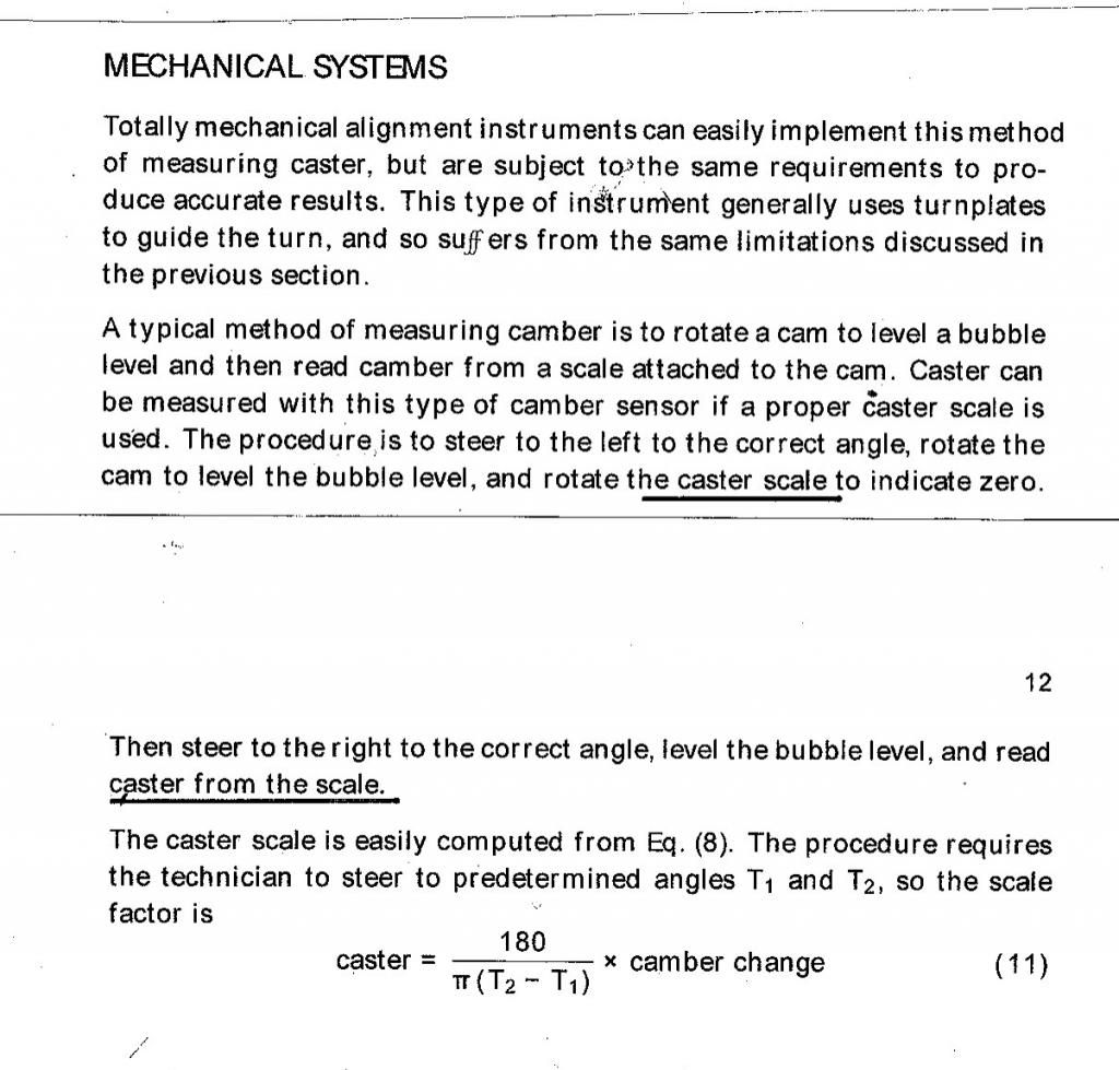
The key issue about the Trakrite guage is contained in the equation on page 12 ; could I suggest that if you can't cope with the maths, then - WADR - posting it doesn't really matter anyway won't move the debate forward very much.

If you plug the 20?/20? swing into this equation, you find out that for every ? in camber change, you're actually seeing 1.4? of caster, and not the 1? Gunson claim.

The camber change ONLY EQUALS the caster change when (Pi x The Swing) = 180, which gives the swing as 57?.
Image

REMEMBER the Trakrite has ONE scale that CLAIMS to do both ; but at 20?/20? it does nothing of the sort.

If you set your 3.8 by this method, instead of getting 2? you'll actually be getting 2.9?.

Sloppy thinking should be punishable by law.

I should get out more often.
Rory
3.8 OTS S1 Opalescent Silver Grey - built May 28th 1962

Link:
BBcode:
HTML:
Hide post links
Show post links

User avatar

PeterCrespin
Posts: 4561
Joined: Fri Mar 05, 2010 8:22 pm
Location: Gaithersburg, Maryland.
Contact:
United States of America

#20

Post by PeterCrespin » Sat Jan 03, 2015 5:36 pm

rfs1957 wrote:I would be the first to agree that it's "how it drives" that counts ; but I do not believe that 1 in a 1000 E-Type owners today have the time and ressources to conduct controlled, repeatable, multi-participant testing on caster-angle optimisation, never mind the inclination to do so, nor the experience to appraise what they're feeling.

And I am certainly not one of them.
Join the club. You are, however, assuming that subtle differences are significant or noticeable from the driver's seat and therefore important to eradicate or to 'get right. It's my guess your 1/1000 holds good here too and that within reason the issue is as much to do with setup symmetry and repeatability as with absolute values.

This is the same as many many factors on the car including engine issues such as crank balance factors, chamber volumes, inlet tract lengths etc. Sure, piston clearances, journal ovality etc. need to be accurate or damge or premature wear ensues, but caster settings? Nah. There isn't even a detectable effect on tyre wear the way there can be with toe or camber.

There's rarely a truly 'perfect' or even 'unequivocal best' value for either original or current day settings, just a choice of adequate compromises. Since most of us struggle to detect differences unless something is way out of spec you will recognise the merit of your adopted countryman Voltaire's aphorism that "Dans ses ?crits, un sage Italien dit que le mieux est l'ennemi du bien."

If the perfect can be the enemy of the good enough, why stress over a variable whose small increments by your own admission are difficult for you and I to measure, or to evaluate the effect of in practice? The 1 in 1000?people who DO take the time and trouble to experiment to the Nth degree and gain special insight for their pains are generally those on the rostrum. The rest of us in mid-field or tail end Charlies just have fun and let the propellor heads up front do their thing. You at least can now relax that there IS a formula for deriving castor from camber change and therefore any non-Jag alignment shop offering to do it for you is on safe ground (or you can trust the crude little Trakrite to get you close enough to be safe, with plenty of easy tinkering if you want to finesse that).

Unlike camber, it's easy to tweak the caster several times during a shakedown run to see how it feels. You don't need to fiddle with shims or gauges like for camber or toe which you can only do in the workshop. An 11/16" open ender for the upper fulcrum flats, plus R clips instead of split pins in the catellated nuts and it takes 2 mins per side without so much as jacking the car up. Mark the fulcrum and count the half-turns as you would on a motorbike chain tensioner, so you can stay parallel each side and remember previous settings. I tried it once and couldn't really tell much difference with the stock 16" steering wheel leverage. Ergo, when I use the Trakrite again next time, I'll leave caster alone at spec.

Pete
1E75339 UberLynx D-Type; 1R27190 70 FHC; 1E78478; 2001 Vanden Plas

Link:
BBcode:
HTML:
Hide post links
Show post links

Post Reply Previous topicNext topic