


I recently bought the third brake light from Marek, connected it all up got a lovely reverse light but no brake light. The unit was tested and it is fine. On checking voltages I only get 9v on the braking circuit. The incandescent bulbs work but obviously dimmer than they ought to be…..need help from anyone who may have ideas why to check etc’. Thanks in advance.
Where does the brake light hydraulic switch reside? is it on the picture frame?
Weird electrical issue
#1 Weird electrical issue
Danny
1962 S1 3.8 FHC (1012/1798)
2015 Range Rover Sport SVR
"Experience is something you don't get until just after you need it."
1962 S1 3.8 FHC (1012/1798)
2015 Range Rover Sport SVR
"Experience is something you don't get until just after you need it."
| Link: | |
| BBcode: | |
| HTML: | |
| Hide post links |

#2 Re: Weird electrical issue
Suggest you consider fitting a mechanical brake light switch. Easy to do and you can leave the hydraulic switch in circuit. Details in the upgrade Forum or you can buy a kit from the usuals.
David Jones
S1 OTS OSB; S1 FHC ODB
1997 Porsche 911 Guards Red
Add your E-Type to our World Map: http://forum.etypeuk.com/viewtopic.php?f=1&t=1810
S1 OTS OSB; S1 FHC ODB
1997 Porsche 911 Guards Red
Add your E-Type to our World Map: http://forum.etypeuk.com/viewtopic.php?f=1&t=1810
| Link: | |
| BBcode: | |
| HTML: | |
| Hide post links |
#3 Re: Weird electrical issue
Thanks will consider, I would still like to know where the stock switch lives.
Danny
1962 S1 3.8 FHC (1012/1798)
2015 Range Rover Sport SVR
"Experience is something you don't get until just after you need it."
1962 S1 3.8 FHC (1012/1798)
2015 Range Rover Sport SVR
"Experience is something you don't get until just after you need it."
| Link: | |
| BBcode: | |
| HTML: | |
| Hide post links |

#4 Re: Weird electrical issue
Hydraulic switch is on the picture frame...just follow a brake line you will find it....only 9v....then you must have a high resistance joint somewhere.. volt drop...Steve
Steve
69 S2 2+2 (just sold) ..Realm C type replica, 1960 xk150fhc
69 S2 2+2 (just sold) ..Realm C type replica, 1960 xk150fhc
| Link: | |
| BBcode: | |
| HTML: | |
| Hide post links |
#5 Re: Weird electrical issue
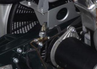
Stock switch is On the front brake circuit. Follow the brake line from the master cylinder forward and you will find a Tee joint just below the header tank support. From there line to go each brake called and the top of the Tee has the pressure switch. Id just replace with new and see if it cures the issue. SNGB sell better quality switches than standard intermotor rubbish that seem to work. That will probably cure the issue. It's a simple job also to wire a relay so the switch operates the relay and the relay deals with the higher load for the bulbs but start by replacing the pressure switch. With the new one to hand you can do a quick unscrew and screw up and probably won't need to bleed the front brake at all...
Julian the E-type man
1962 FHC
1966 MGB....fab little car too
1962 FHC
1966 MGB....fab little car too
| Link: | |
| BBcode: | |
| HTML: | |
| Hide post links |

#7 Re: Weird electrical issue
Thank all, I did but couldn't see it yet, it was too hot so gave up, will get her in the warehouse tomorrow and pursue it further.
Danny
1962 S1 3.8 FHC (1012/1798)
2015 Range Rover Sport SVR
"Experience is something you don't get until just after you need it."
1962 S1 3.8 FHC (1012/1798)
2015 Range Rover Sport SVR
"Experience is something you don't get until just after you need it."
| Link: | |
| BBcode: | |
| HTML: | |
| Hide post links |
#8 Re: Weird electrical issue
Danny,
My brake light didn’t work initially as the voltage had dropped below the point at which the LED had enough juice to light up. From Marek at the time;
There are two inline diodes also supplied. You may not need them. Connected one way, a diode blocks voltage from getting through; connected the other way, a silicon diode will drop the operating voltage by 0.7volts.
The one line summary of the instructions is "Don't put too high a voltage onto the green/brown wire - measure it first and put an inline diode into the white LED circuit"
Instructions
LEDs are different from filament bulbs in that they have a minimum voltage below which they do not light at all, as opposed to filament bulbs, which simply glow more weakly at low voltage. LEDs also have a recommended operating voltage, which if exceeded, causes them to draw more current, light brighter and overheat. This unit comprises units of six red LEDs in series and groups of four white LEDs in series.
There are a lot of misconceptions about electricity in automobiles. People often refer to "12v" and "battery voltage", but a battery is only used to start a car. Once the engine has started, it is alternator voltage which matters, not battery voltage. The battery only acts to smooth out the charging pulses of the alternator.
A typical battery is charged to about 12.6-12.8 volts. Electric power is provided by the alternator. This is usually set between 14 to 14.4 volts.
The white LEDs are 3.2-3.4volt LEDs, so their operating voltage is 12.8 to 13.6volts. A typical car will have wiring with multiple connectors between its battery/alternator and the back of the car, such that approximately 0.6volts are lost between the front and back of the car. A typical alternator is set to charge the battery at a maximum of 14.4volts, so the maximum expected voltage at the back of the car is 13.8volts. If the measured voltage at the back of the car is higher than this, with the alternator running and the engine revs at 3000rpm, then the diode supplied should be fitted inline with the green/brown wire to the unit. The diode only allows current to flow in one direction, so it should be inserted with the white bar towards(away from) the unit on a negative(positive) earth car. The effect this will have is to drop the delivered voltage by 0.7volts, bringing the operating voltage for the green/brown wire down to a safe level.
The red LEDs are 2-2.2volt LEDs, so their operating voltage is 12-13.2volts. They sit behind a voltage regulator which sets the voltage at 12volts, but to do this, it requires an overhead of about 1.2volts, so the red LEDs operate at maximum brightness when supplied with a minimum of 13.2volts to the red wire. There is no maximum voltage as the regulator handles this. This means that the red LEDs will illuminate only weakly under battery voltage alone, but come up to full brightness once the alternator is running.
If the diode is not required to drop the operating voltage for the white LEDs, then it can be used to wire up the red LEDs to act as a fog lamp AND as a stop light. To do this, take a feed from the stop light 12v (typically red/purple), place the diode inline using a spare two way female bullet connector with the white bar pointing towards the unit and fit a four way female bullet connector to it. The red wire of the unit can now also be connected to the four way connector, as can the red/yellow fog light feed. The diode now acts to stop a backfeed of voltage from the fog light to the car's original stop lights. This allows the stop lights to function as before, i.e. feed 12v to unit when the brake pedal is pressed and also to act as a fog light if the red/yellow wire is energised - but crucially, to not allow the fog light 12v to get to the car's original stop lights.
The black wire must be securely bolted to the chassis.
Steve
1965 S1 4.2 FHC (early)
1965 S1 4.2 FHC (early)
| Link: | |
| BBcode: | |
| HTML: | |
| Hide post links |
#9 Re: Weird electrical issue
Use the circuit diagram to follow the path from the battery/alternator through every bullet connector, fuse and component on the path to the back of the car and see where your voltage drop occurs by measuring the voltage at each stage. Then you'll need to address what to do about it. A three volt drop is excessive. An original car will likely see a drop of 0.6-0.8v.
An alternative methodology, with the battery disconnected, is to measure the resistance along the path from point to point. Ideally, there ought not to be any.
On the plus side, you will now have visible brake lights.... which you probably haven't had for several years.
kind regards
Marek
An alternative methodology, with the battery disconnected, is to measure the resistance along the path from point to point. Ideally, there ought not to be any.
On the plus side, you will now have visible brake lights.... which you probably haven't had for several years.
kind regards
Marek
| Link: | |
| BBcode: | |
| HTML: | |
| Hide post links |
#10 Re: Weird electrical issue
This kit looks more substantial than some of the weaker offerings around:
Part No. C16062MODE
http://www.ajautocraft.co.uk/partsWithPic.htm

Steve
1965 S1 4.2 FHC (early)
1965 S1 4.2 FHC (early)
| Link: | |
| BBcode: | |
| HTML: | |
| Hide post links |
#11 Re: Weird electrical issue
Thanks Marek, I did intend to mostly follow your suggestion but the very first step was to measure the voltage on the switch ip/op to verify the voltage at the starting point. Thanks all for the link s to the upgrade kits which I will consider all else failing.
Danny
1962 S1 3.8 FHC (1012/1798)
2015 Range Rover Sport SVR
"Experience is something you don't get until just after you need it."
1962 S1 3.8 FHC (1012/1798)
2015 Range Rover Sport SVR
"Experience is something you don't get until just after you need it."
| Link: | |
| BBcode: | |
| HTML: | |
| Hide post links |
#12 Re: Weird electrical issue
As others have already pointed out, the obvious answer is often the right answer:- I'd measure the resistance across the brake switch and then apply the brakes. It should go from infinity straight to less than one ohm. Multimeters generally can't measure anything lower than that but the reading should be no different than if the test leads were simply connected to each other.
kind regards
Marek
kind regards
Marek
| Link: | |
| BBcode: | |
| HTML: | |
| Hide post links |
#13 Re: Weird electrical issue
Once I locate the switch.....and I did, it is in a very awkward location on mine just under the bottom hose of the radiator, there is just enough reach it to disconnect the wires, not going to bother with it and go straight for a mechanical upgrade.
Danny
1962 S1 3.8 FHC (1012/1798)
2015 Range Rover Sport SVR
"Experience is something you don't get until just after you need it."
1962 S1 3.8 FHC (1012/1798)
2015 Range Rover Sport SVR
"Experience is something you don't get until just after you need it."
| Link: | |
| BBcode: | |
| HTML: | |
| Hide post links |
#14 Re: Weird electrical issue
Post updated. ordered the kit from AJautocraft.
Danny
1962 S1 3.8 FHC (1012/1798)
2015 Range Rover Sport SVR
"Experience is something you don't get until just after you need it."
1962 S1 3.8 FHC (1012/1798)
2015 Range Rover Sport SVR
"Experience is something you don't get until just after you need it."
| Link: | |
| BBcode: | |
| HTML: | |
| Hide post links |
-
 ralphr1780
- Posts: 1067
- Joined: Wed Apr 11, 2012 4:29 pm

#15 Re: Weird electrical issue
Danny, at first bridge the 2 wires on the hydraulic switch. If you get battery voltage and the new stop light goes on, then you have only a defective switch. If it does not, then you have to start investigating all the line bullets.
Are you with positive or negative ground ?
As this reverse light is anyway too low for good visibility by current standards, personally have used it as a rear fog light and fitted a 3rd brake light on the trunk lid (ots), this is way better visible.
Are you with positive or negative ground ?
As this reverse light is anyway too low for good visibility by current standards, personally have used it as a rear fog light and fitted a 3rd brake light on the trunk lid (ots), this is way better visible.
Ralph
'69 OTS + '62 OTS - Belgium
'69 OTS + '62 OTS - Belgium
| Link: | |
| BBcode: | |
| HTML: | |
| Hide post links |
#16 Re: Weird electrical issue
Thanks, sound advise.
Danny
1962 S1 3.8 FHC (1012/1798)
2015 Range Rover Sport SVR
"Experience is something you don't get until just after you need it."
1962 S1 3.8 FHC (1012/1798)
2015 Range Rover Sport SVR
"Experience is something you don't get until just after you need it."
| Link: | |
| BBcode: | |
| HTML: | |
| Hide post links |
#17 Re: Weird electrical issue
Update: The hydraulic switch stopped working all together, checking the electrical connections on the switch shows a low voltage on the switch itself meaning there must be some bad connection to 12V supply at source or somewhere on the way. In the mean time I have received the mechanical switch conversion kit which I shall be fitting next week as I had no time to deal with it up to now. wish me luck.
Danny
1962 S1 3.8 FHC (1012/1798)
2015 Range Rover Sport SVR
"Experience is something you don't get until just after you need it."
1962 S1 3.8 FHC (1012/1798)
2015 Range Rover Sport SVR
"Experience is something you don't get until just after you need it."
| Link: | |
| BBcode: | |
| HTML: | |
| Hide post links |
#18 Re: Weird electrical issue
As I said in post 4....Steve
Steve
69 S2 2+2 (just sold) ..Realm C type replica, 1960 xk150fhc
69 S2 2+2 (just sold) ..Realm C type replica, 1960 xk150fhc
| Link: | |
| BBcode: | |
| HTML: | |
| Hide post links |
#19 Re: Weird electrical issue
The instructions printed above for Marek's LED units infer that a voltage driven design is being used; if so that is poor design practice as LEDs must be used in a current driven environment if they are to operate reliably and with a long life.
Your brake lights are a safety critical item. We need to be careful here.
Your brake lights are a safety critical item. We need to be careful here.
John
1969 Series 2 FHC
1969 Series 2 FHC
| Link: | |
| BBcode: | |
| HTML: | |
| Hide post links |
#20 Re: Weird electrical issue
Dear John,
1/ A graph of voltage versus current for LEDs shows they are a straight line relationship. Current is always controlled by limiting the voltage. It's usually done with an inline feedback resistor. You seem to have forgotten that the alternator limits the voltage to start with.
2/ Now read the instructions again - your comments can only pertain to the white reversing light! The red LEDs have a regulated supply.
3/ Finally, you seem not to have noticed that the red LEDs are "extra" - they don't interfere or affect the operation your current brake lights in any way.
Assuming you follow the instructions, to break these units, you are going to have to either physically break components off of the board, dowse the unit in water or suffer an alternator/regulator failure. Even with the alternator overvoltage scenario, you are going to have to ignore your battery acid boiling out, your lights burning out, coil overheating etc and then additionally put the car into reverse gear and keep it there long enough to burn out the white LEDs. Good luck with that.
I have only seen three failures in fifteen years. Two were water damaged due to not using gaskets - the rust gave it away. The third was because one enterprising owner fitted an alternator "upgrade" which output too high a voltage and had no way of dropping the voltage down to a safe level. He continues to overcharge his battery despite best advice and will one day enjoy the joyous benefits of breakdown assistance that his motor insurance policy provides. That's why something with just two wires and an earth connection needs two whole pages of instructions.
kind regards
Marek
| Link: | |
| BBcode: | |
| HTML: | |
| Hide post links |