Routing of Front Wiring Harness Engine Bay - experiences of others ?

Talk about the E-Type Series 1
User avatar

Topic author
rfs1957
Posts: 1325
Joined: Sat Jan 15, 2011 2:52 pm
Location: Languedoc - France
France

#1 Routing of Front Wiring Harness Engine Bay - experiences of others ?

Post by rfs1957 » Sun Jan 14, 2024 12:11 pm

Just to distract you all on a Sunday, before the wiring topic, how about these for a wardrobe find chez a distant aunt, whom we knew went to Le Mans in 1957 ............

Image

Image

Image

Two weeks before my birthday ............. 278 km/h on the Mulsanne straight.

It makes you want to go and get your D-Type finished ; looks like I'll have to make do with an E, sniff.

I've been unable to find anything very specific about how the harness should be actually run along and around the front frames, so am posting these pictures as a possible/probable routing, in the hope that others may either confirm or correct them.

They show an Autosparks "Part Number 101 3.8 Engine Bay Wiring Harness - with Fan Relay" dating from September 2023.

This is a preliminary lash-up just to check that the run is feasible and the wires are going to reach.

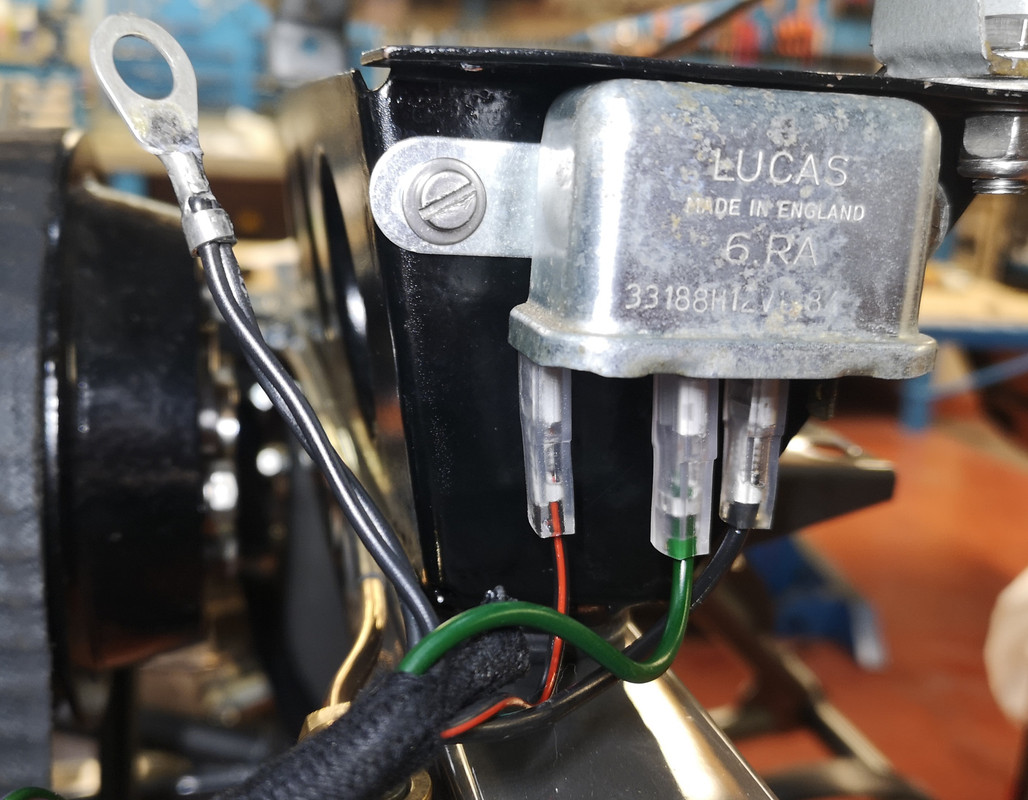
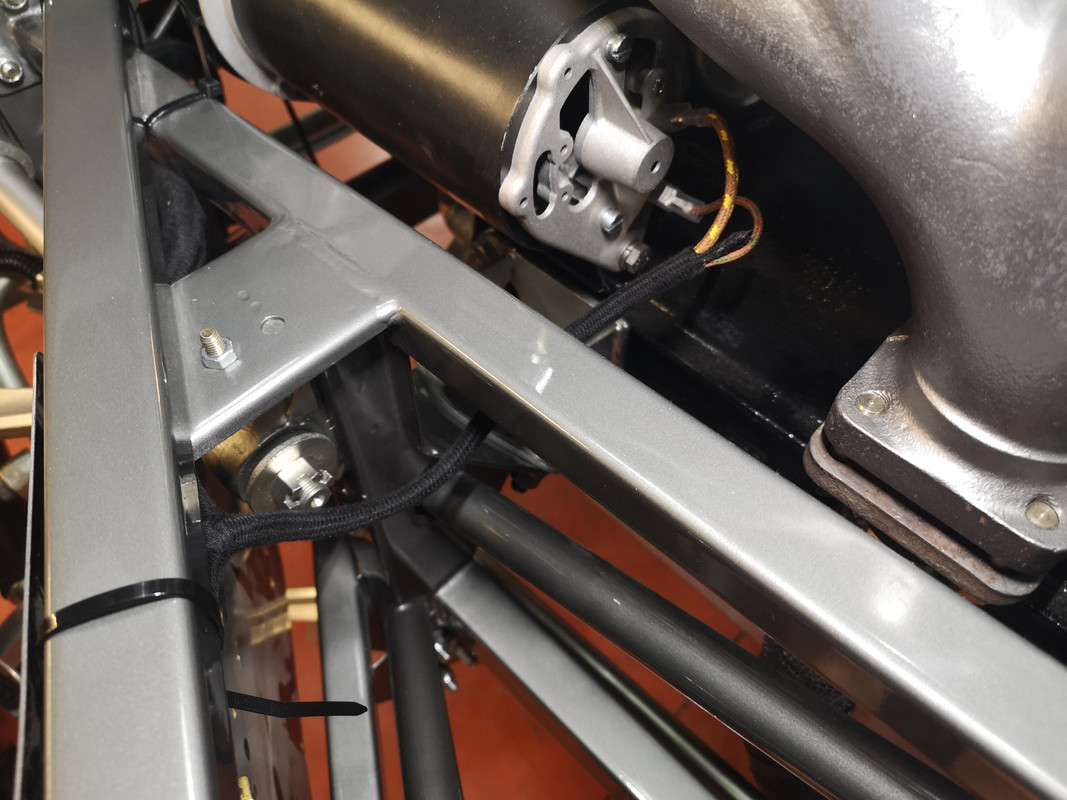
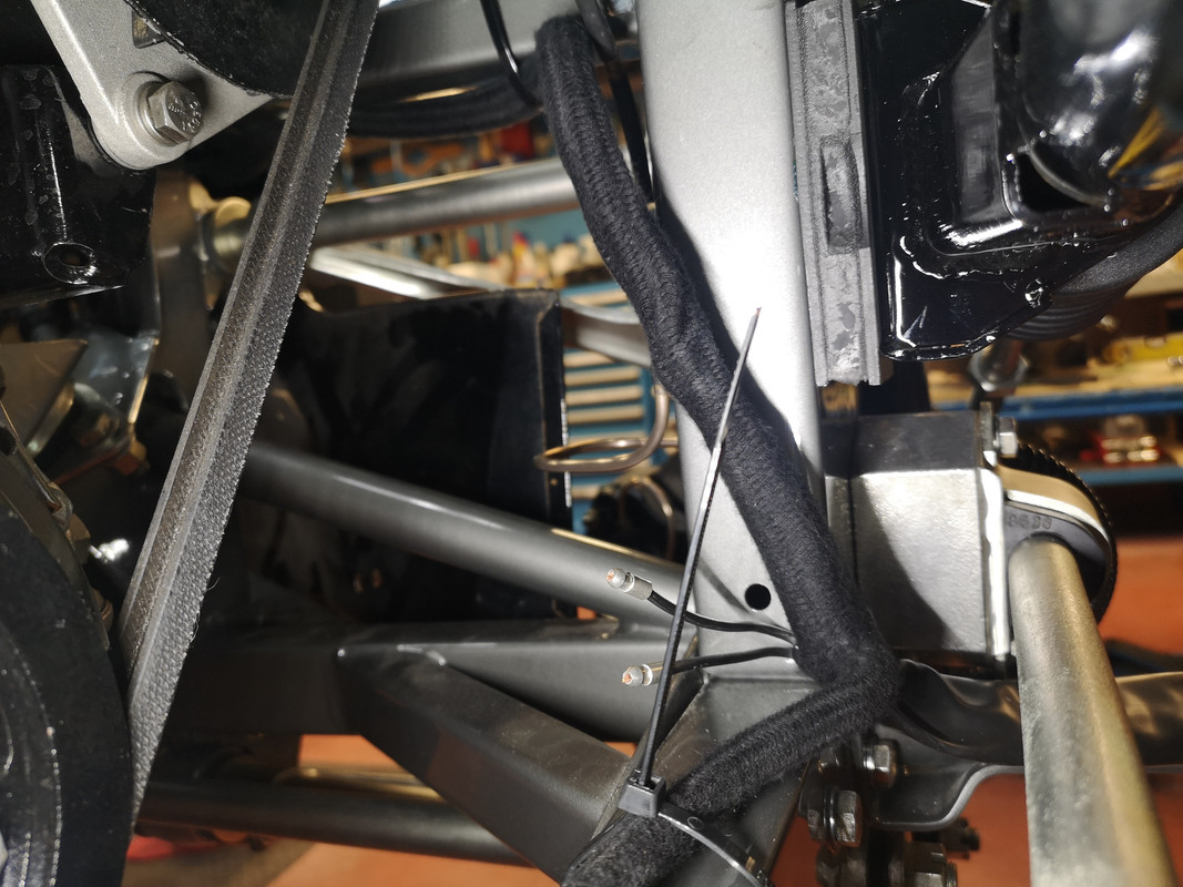
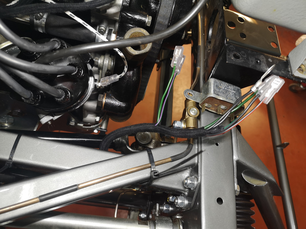
The starting point seems to be fixed, just behind the RB340 regulator,

Image

Image

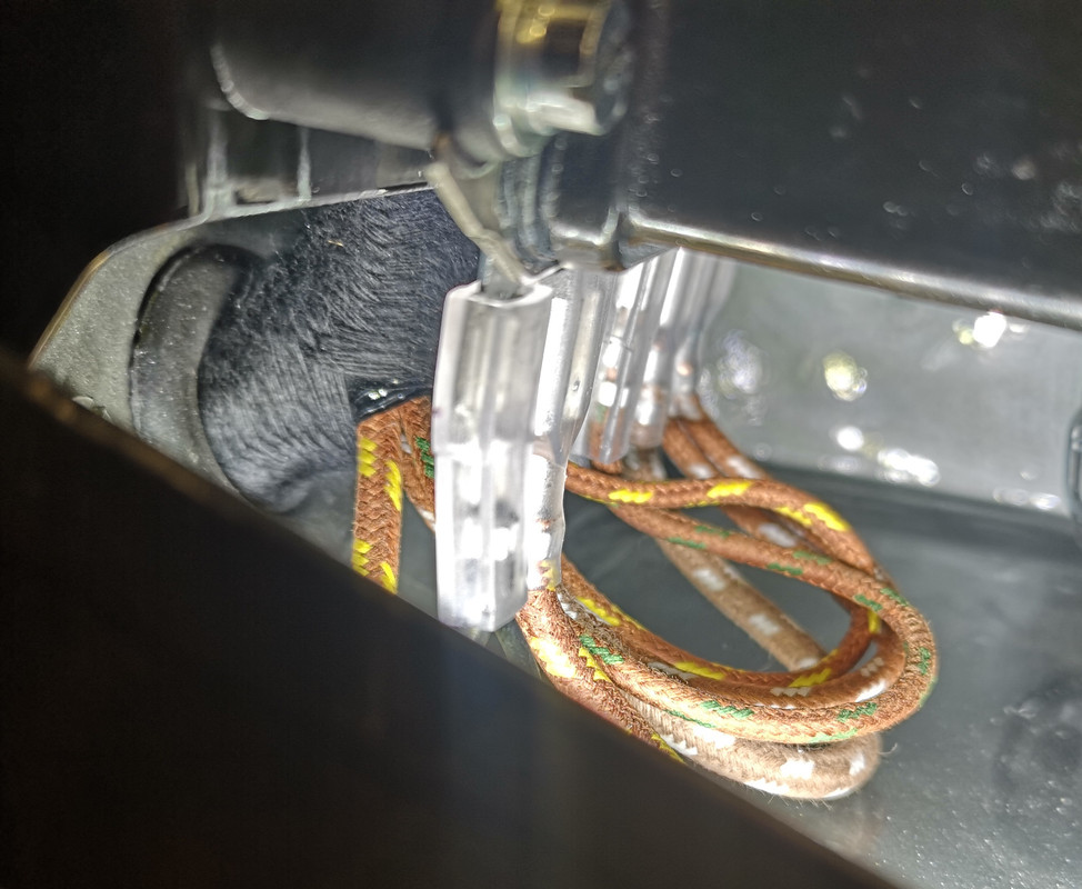
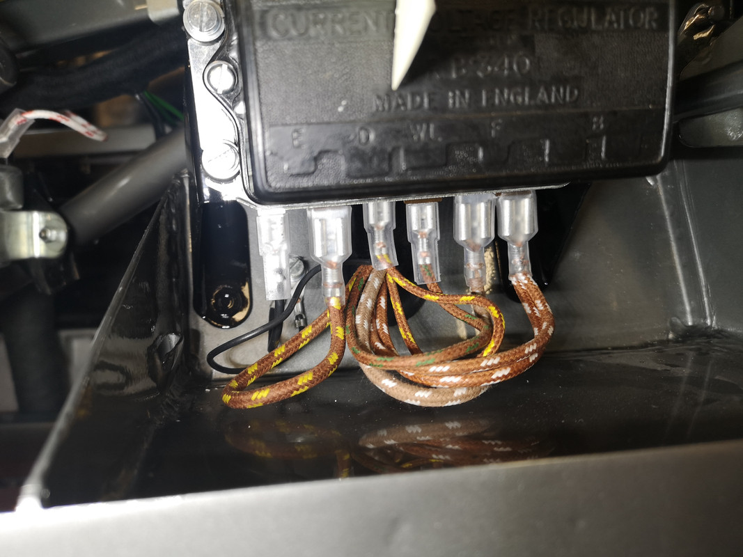
so there's not much choice about the initial run upwards, and from then on I've elected to run the harness underneath the upper square tube :

Image

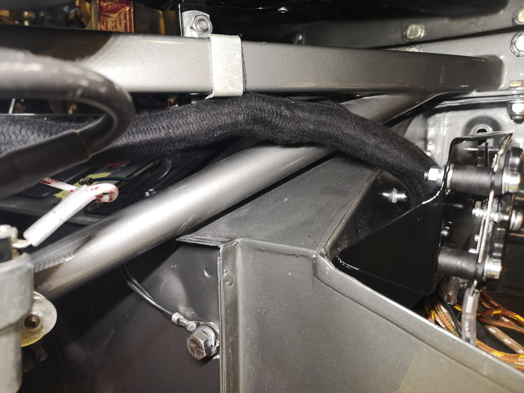
as this seems to optimise the exits for the main harness earth to the toe board, and the heater-fan wires :

Image

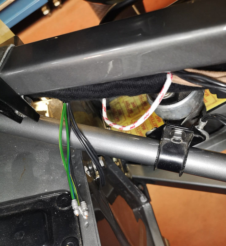
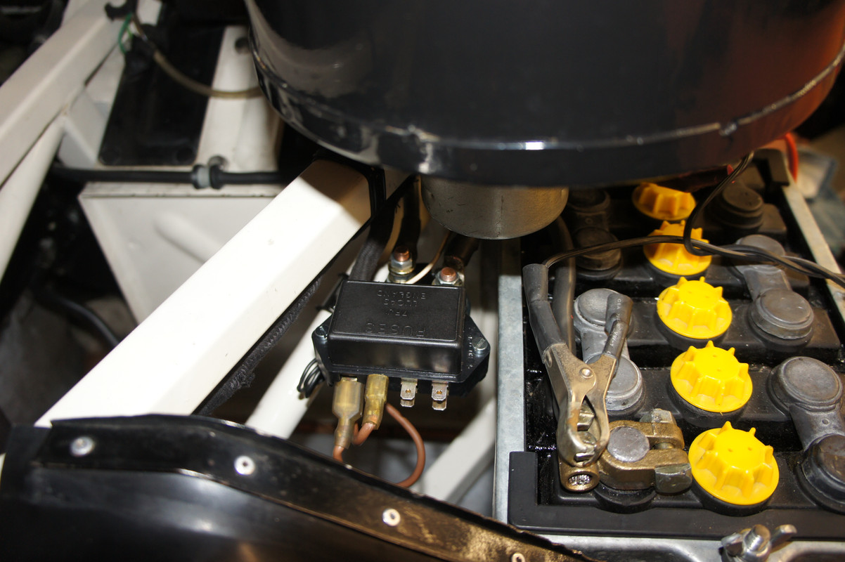
followed by the white/red of the starter motor relay (is mine in the correct location ?), the two browns, one feeding fuses F3 and F8 (that don't go through the ammeter), the other the ammeter :

Image

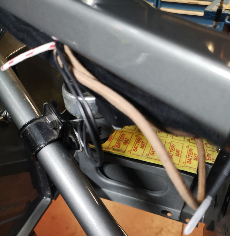
Next is the exit for the horn-relay wires :

Image

- at this point, if anything I felt that the harness was getting a bit "ahead of itself" and had to consciously "use up" a few inches nearer to the heater/regulator so that the approach of the relay wires was more comfortable.

Next is the dynamo/fake-alternator spur, which looks logical and correct.

Image

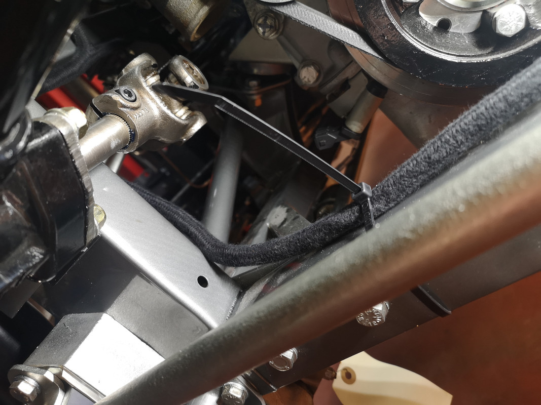
I'm guessing that at this point the harness remains below the square frame tube, and dives inside to drop vertically down the inside of the picture frame ?

Image

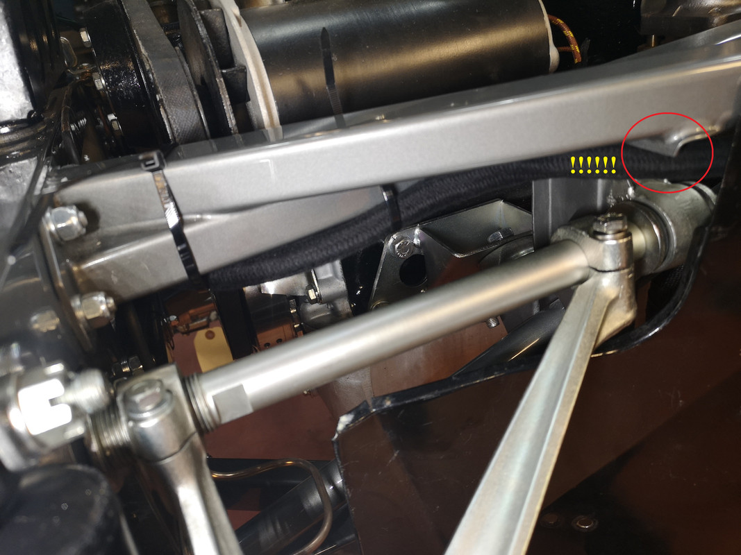
Warning - if this IS correct, beware of this rib on the frame bracket - in an earlier incarnation of my car this edge was quite sharp, and had contrived to cut through the harness sleeving, and through the fat red/yellow wire as far as the copper ......... on cars with a 4-position lighting switch, it was destined to feed fog-lamps through a further last click on the switch, (terminal 12 on the wiring diagram, page 354 of the Bentley Workshop Manual) where I had - very fortunately - never ventured, as it would have ignited the whole harness, the main brown feed to the lighting switch being completely unfused ............

There's a lot about this here :

viewtopic.php?f=3&t=5214&p=36869&hilit=fuse#p36869

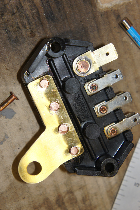
and my attempt to make safer / more robust the fusing of the wiring harness, resulting in this modification - which is entirely compatible with the original harness.

Image

Image

Image

But I digress ........

Having turned inside, running behind the picture frame, the harness seems to reach a logical split at the foot of the picture frame :

Image

- with the plastic-sleeved bonnet harness running off towards the front, and the main harness continuing along the top - should that be across the front ? - of the lower picture frame traverse.

Image

I found it rather puzzling that the fan-wires that exit at this same point should be so short, and am guessing that the fan itself must have had quite a long harness to get there ? My car doesn't use the original fan so I'm none the wiser ............

Image

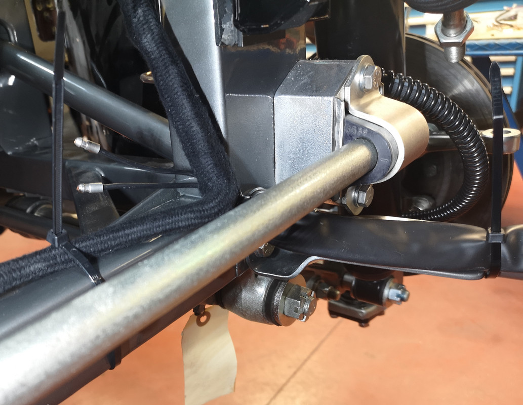
Having run along the lower picture-frame traverse, It then seems to want to run up behind its right hand vertical :

Image

- seen here, pictured from the rear :

Image

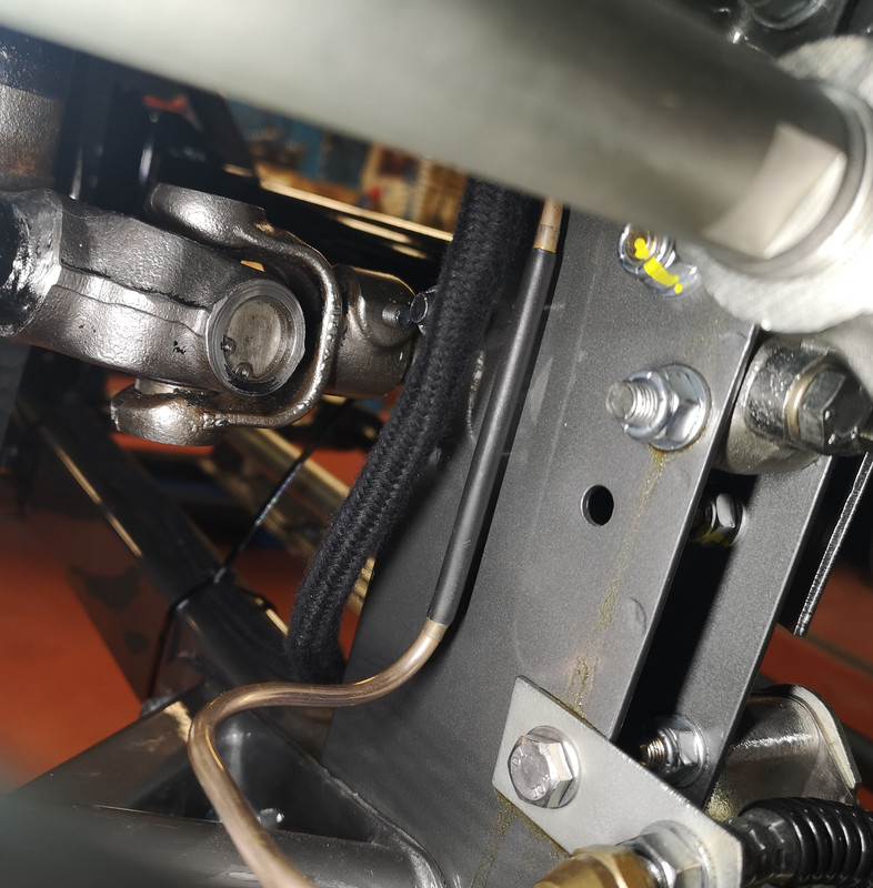
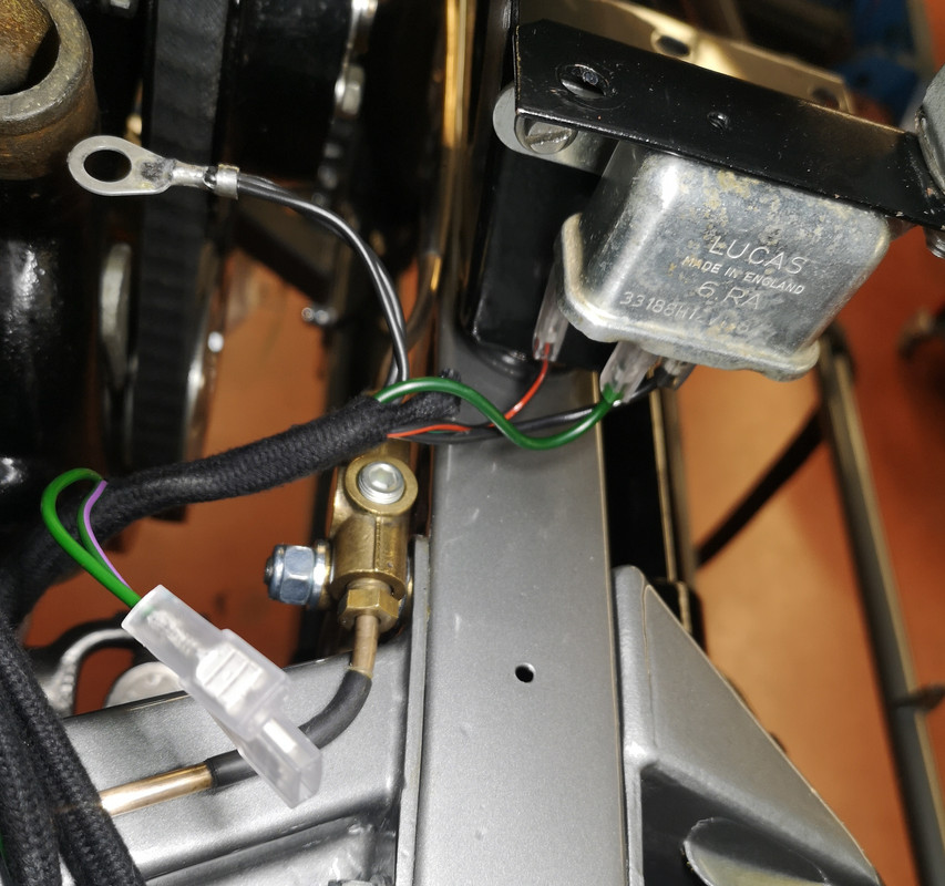
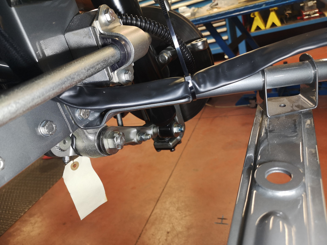
and then run, like on the LHS, underneath the square front-frame tube :

Image

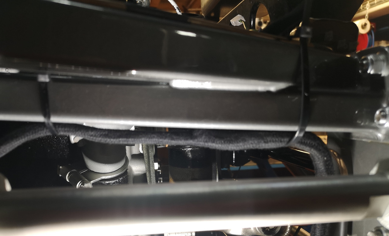
where spurs emerge to feed the hydraulic stop-light switch (not used on my car) and the original fan-relay :

Image

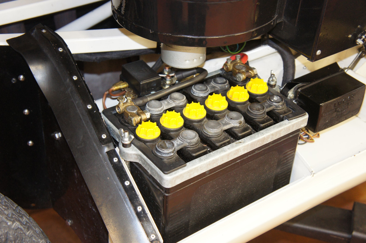
The harness is rather generous at this point and I'm guessing it was intended to run around the back of the distributor as shown ? The white/brown on the left runs off to the oil-pressure sensor.

Image

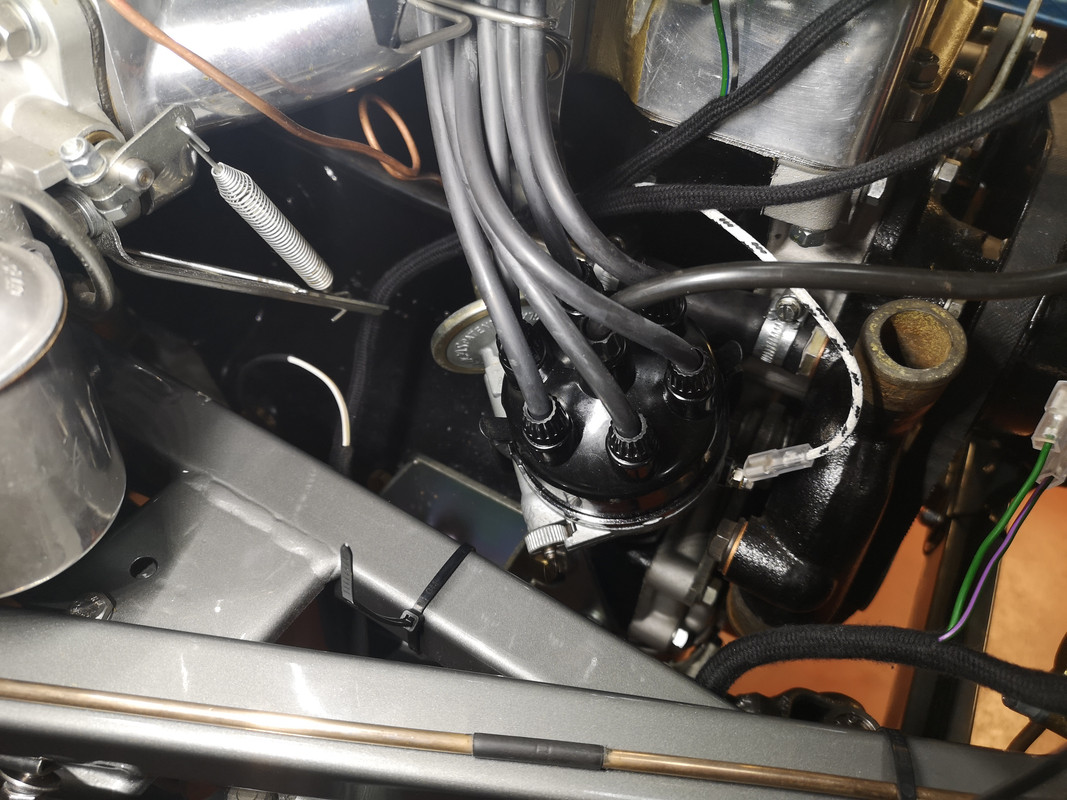
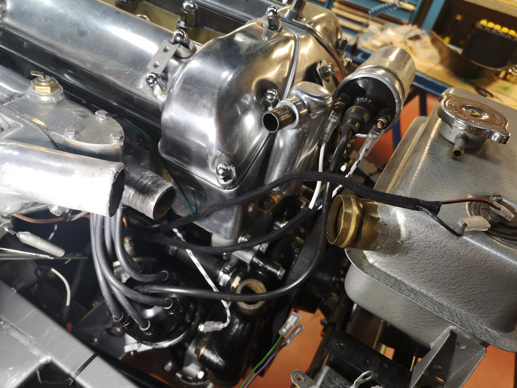
- and the remaining spurs go to the white/black of the distributor, that reappears along with the white ignition feed to the coil, plus the earth and black/red for the otter-switch :

Image

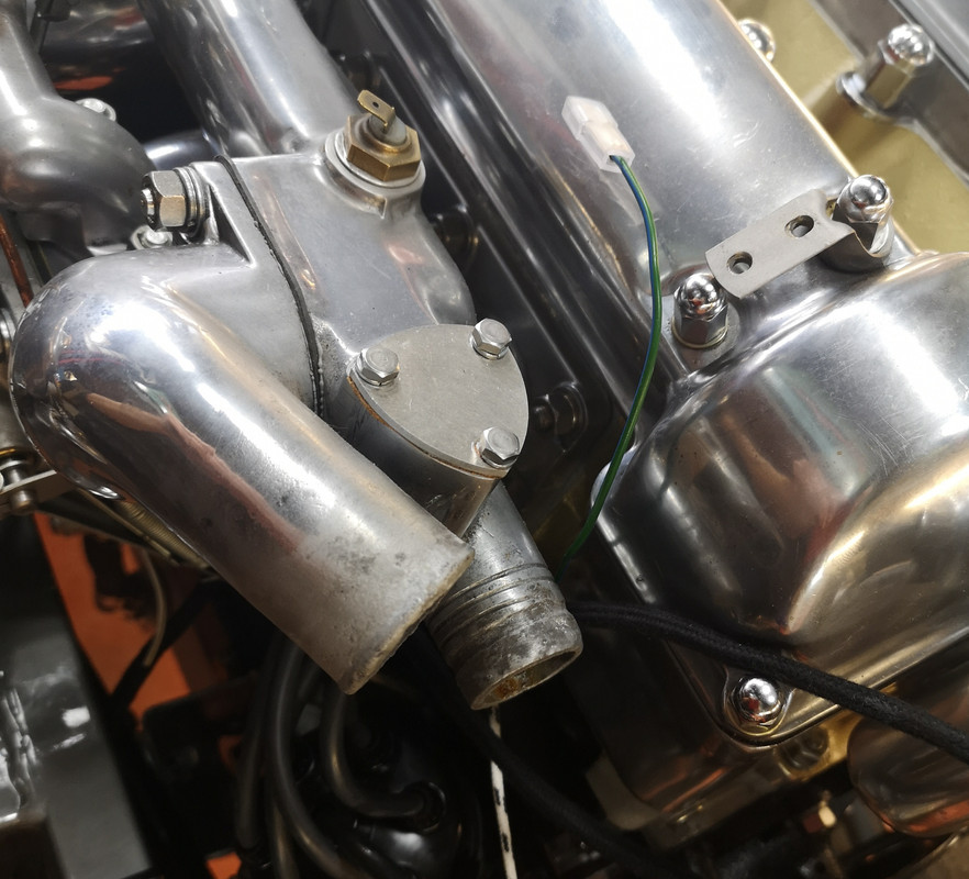
There seems nevertheless to be a bit of an orphan here, in that the green/blue destined for the water-temperature sensor is too short to have a comfortable run to the spade connector, on mine at least - has anyone else had this issue ? Autosparks seem very responsive regarding suggestions about their harnesses and it might be worth passing them that feedback ..........

Image

If anyone else has done this recently, and did things differently, I'd be grateful to hear from them.
Rory
3.8 OTS S1 Opalescent Silver Grey - built May 28th 1962

Link:
BBcode:
HTML:
Hide post links
Show post links

User avatar

paydase
Posts: 556
Joined: Thu Dec 19, 2013 7:11 am
Location: Belgium
Belgium

#2 Re: Routing of Front Wiring Harness Engine Bay - experiences of others ?

Post by paydase » Sun Jan 14, 2024 2:21 pm

Nothing useful to add on the harness, Rory.
But nice find, these hictoric newspapers of Le Mans 1957!
At that time, Le Mans was "the race", F1 was not that famous.
Serge
1964 (3.8) FHC
1961 OTS

Link:
BBcode:
HTML:
Hide post links
Show post links


christopher storey
Posts: 5698
Joined: Sun Mar 09, 2008 3:07 pm
Location: cheshire , england
Great Britain

#3 Re: Routing of Front Wiring Harness Engine Bay - experiences of others ?

Post by christopher storey » Sun Jan 14, 2024 2:27 pm

Rory : the way mine was done originally, and the ( same) way I adopted on my rebuild, was the way you have done yours i.e. around the top rail positioned on the rail's underside, and I cannot recall having seen it done in any other way except that one car positioned the harness on the inside of the top rail . I did not like this : it exposes the harness to more heat in , on the left side at any rate , an already hot area

Link:
BBcode:
HTML:
Hide post links
Show post links

User avatar

caveman
Posts: 498
Joined: Sun Nov 18, 2007 10:55 am
Great Britain

#4 Re: Routing of Front Wiring Harness Engine Bay - experiences of others ?

Post by caveman » Sun Jan 14, 2024 5:04 pm

Rory,
Dont forget the correct cable ties/strapping;

Image
Steve
1965 S1 4.2 FHC (early)

Link:
BBcode:
HTML:
Hide post links
Show post links

User avatar

mgcjag
Moderator
Posts: 8100
Joined: Fri Jul 09, 2010 6:15 pm
Location: Ludlow Shropshire
Great Britain

#5 Re: Routing of Front Wiring Harness Engine Bay - experiences of others ?

Post by mgcjag » Sun Jan 14, 2024 5:41 pm

White strapping studs for early cars also available from SNGB......Steve
Steve
69 S2 2+2 (just sold) ..Realm C type replica, 1960 xk150fhc

Link:
BBcode:
HTML:
Hide post links
Show post links

User avatar

Topic author
rfs1957
Posts: 1325
Joined: Sat Jan 15, 2011 2:52 pm
Location: Languedoc - France
France

#6 Re: Routing of Front Wiring Harness Engine Bay - experiences of others ?

Post by rfs1957 » Sun Jan 14, 2024 8:03 pm

Repeat after me : "I promise not to use zip cable ties on the final version".

Image

viewtopic.php?f=3&t=9131&p=71286&hilit=ties#p71286

I got laughed at in the playground seven years ago with my tightening-tool, but I swear it does a good job and that I'll be using it again :hammerdrill:

A fool and his tools are not easily parted.
Rory
3.8 OTS S1 Opalescent Silver Grey - built May 28th 1962

Link:
BBcode:
HTML:
Hide post links
Show post links

User avatar

Allrand
Posts: 400
Joined: Tue Dec 08, 2020 10:45 am
Location: Kempton Park, South Africs
South Africa

#7 Re: Routing of Front Wiring Harness Engine Bay - experiences of others ?

Post by Allrand » Mon Jan 15, 2024 7:15 am

I did mine generally following the same route as you. I can't quite see how you crossed the picture frame from left to right, did you go along the bottom frame or the top. I've seen some pictures going along the bottom but to my mind it exposes it to too much dirt & grime, I went along the underside of the top frame.
Randall Botha
'64 3.8 fhc & '51 Mk 7

Link:
BBcode:
HTML:
Hide post links
Show post links

User avatar

Topic author
rfs1957
Posts: 1325
Joined: Sat Jan 15, 2011 2:52 pm
Location: Languedoc - France
France

#8 Re: Routing of Front Wiring Harness Engine Bay - experiences of others ?

Post by rfs1957 » Mon Jan 15, 2024 12:24 pm

The exit for the bonnet sheath is positioned, to my mind, in such a way that no other run is possible.

At least with this Autosparks loom.

If you stay high, on the top picture frame traverse, the bonnet bifurcation would be somewhere around the water pump pulley.

And once you got to the fan-relay and ignition spurs you would have ten or twelve inches of loom too much.

And now I think of it, the factory drawing in the KBase clearly shows the harness dropping.

So am pretty confident this is correct.
Rory
3.8 OTS S1 Opalescent Silver Grey - built May 28th 1962

Link:
BBcode:
HTML:
Hide post links
Show post links

User avatar

Topic author
rfs1957
Posts: 1325
Joined: Sat Jan 15, 2011 2:52 pm
Location: Languedoc - France
France

#9 Re: Routing of Front Wiring Harness Engine Bay - experiences of others ?

Post by rfs1957 » Wed Jan 17, 2024 8:42 pm

Wondering if anyone can throw any light on this earth ?

There's a 5/16 eyelet earth terminal, carrying two blacks, that accompanies the heater-relay spur, where it's mounted on the RHS of the header-tank cradle.

Image

It's also therefore adjacent to the hydraulic stop-light switch location.

This earth serves no purpose for the relay - the earthing it requires to latch comes from the black-red otter switch, and even less for the stop-light switch.

Image

The 5/16 eyelet makes me wonder if it's not meant to go on a front-frame bolt, but why ?

What am I missing please ?
Rory
3.8 OTS S1 Opalescent Silver Grey - built May 28th 1962

Link:
BBcode:
HTML:
Hide post links
Show post links

User avatar

paydase
Posts: 556
Joined: Thu Dec 19, 2013 7:11 am
Location: Belgium
Belgium

#10 Re: Routing of Front Wiring Harness Engine Bay - experiences of others ?

Post by paydase » Wed Jan 17, 2024 9:21 pm

Rory,
On my 61 (LHD), the eyelet of this fourth wire is earthed on the nearby bolt on the frame, where your stop light switch is bolted.
On my car, that stop light switch is bolted on the left side of the car (on the mirroring bolt on the frame), not the right one as yours.
To note (not sure it is relevant though), my car was converted to negative earth.
Serge
1964 (3.8) FHC
1961 OTS

Link:
BBcode:
HTML:
Hide post links
Show post links

User avatar

Allrand
Posts: 400
Joined: Tue Dec 08, 2020 10:45 am
Location: Kempton Park, South Africs
South Africa

#11 Re: Routing of Front Wiring Harness Engine Bay - experiences of others ?

Post by Allrand » Thu Jan 18, 2024 5:53 pm

I would think it bolts to the header tank bracket which is rubber mounted so not earthed.
Randall Botha
'64 3.8 fhc & '51 Mk 7

Link:
BBcode:
HTML:
Hide post links
Show post links

User avatar

paydase
Posts: 556
Joined: Thu Dec 19, 2013 7:11 am
Location: Belgium
Belgium

#12 Re: Routing of Front Wiring Harness Engine Bay - experiences of others ?

Post by paydase » Thu Jan 18, 2024 9:43 pm

As I said above, in my case, on the bolt attaching the top right side frame to the picture frame :
P1240406.jpg
P1240406.jpg (247.09 KiB) Viewed 1304 times
Now I am not sure it is the original mounting...
(and please ignore that header tank :?: )
Serge
1964 (3.8) FHC
1961 OTS

Link:
BBcode:
HTML:
Hide post links
Show post links

Post Reply Previous topicNext topic