


Head removal tool
-
 lowact
Topic author - Posts: 630
- Joined: Mon Oct 09, 2017 10:05 am
- Location: Canberra, Australia
- Contact:

#1 Head removal tool
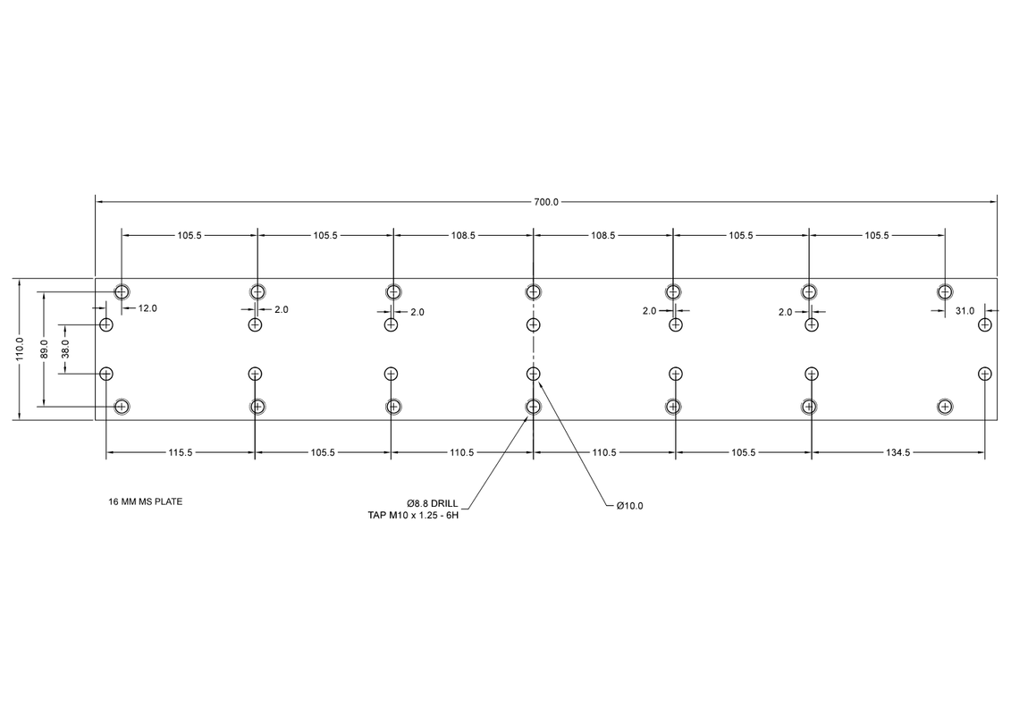
I'm having a head removal tool made. These are the dimensions I've measured/interpreted. Pls, does anyone know any better?
Regards,
ColinL
'72 OTS manual V12
ColinL
'72 OTS manual V12
| Link: | |
| BBcode: | |
| HTML: | |
| Hide post links |

#2 Re: Head removal tool
Have a look at the last few posts here on jag-lovers where Philip posted dimensions https://forums.jag-lovers.com/t/v12-eng ... /134514/17
Bob
'71 S3
'71 S3
| Link: | |
| BBcode: | |
| HTML: | |
| Hide post links |
#3 Re: Head removal tool
Hello Collin,
The Head Pulling Device you're having made is the single plate type. In this system the bolts that push against the Head Studs will tend to want to slide off the top surface of the Stud. Accordingly, have support sleeves made, approximately 12mm longer than the length of the Stud protruding from the Head. The bore should be a close clearance fit on the Stud (7/16" - 11.11mm).
For the same reason, the holes you're having drilled and tapped 10 x 1.25 should be tapped 7/16 UNF (same diameter as the Head Studs). The sleeves are to keep the Jacking Bolts centred on the Head Studs until they enter the Head Stud bores in the Head; from that point on, the Head Stud bores will keep the Jacking Bolts centred. A sleeve can be made to accommodate the 10mm bolt, but the smaller diameter Jacking Bolt will still want to wander off the centre and drag more on the Head Stud bore than if it was a closer fit (same diameter as Head Stud) in the bore.
I can supply you with a drawing in DXF format for the Two Plate system. This system doesn't suffer from the Jacking Bolts wandering off centre of the Head Studs, as non rotating push rods contact the Head Studs and the two plates drawn towards each other.
Best regards,
'
Bill
| Link: | |
| BBcode: | |
| HTML: | |
| Hide post links |
-
lowact
Topic author - Posts: 630
- Joined: Mon Oct 09, 2017 10:05 am
- Location: Canberra, Australia
- Contact:
#4 Re: Head removal tool
Thx, gents, to ask is to learn; redesign req'd.
Phil's dwg reminds me that the two camshafts are different lengths, so additional pair of holes req'd.
I had not appreciated that the principal benefit of the 2-plate design is that the bolts don't rotate, highly desirable imo. I'm going to try and achieve this with a single plate, by using nuts under the plate instead of threading the plate, i.e.:
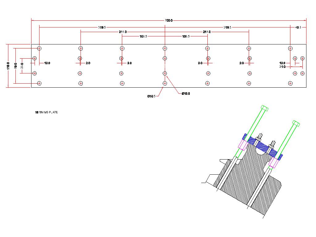
By tightening the nuts while holding the bolts.
The most economical design?
16 mm thick plate will reach up to the thread on the hold-down (tappet block) studs, also close tolerance holes 16 mm long should provide good guidance for the jacking screws.
M10 nuts are the largest that can fit under the plate next to the tappet block, 7/16 is just a smiggin too big, also M10 setscrews are readily available in the length and grade required.
A disadvantage of this design is that I will be torqueing with an open spanner; long (connector) nuts are used to extend to where there will be enough room for the head of the spanner.
10 mm holes for the hold-down (tappet-block) studs should provide enough wriggle room to accommodate any bolt position measurement error, hopefully no worse than Phil achieved, I note his running dimensions swap from head studs to tappet studs half way along, I don't imaging that was intentional.
Hopefully plate will be ready next week ...
Phil's dwg reminds me that the two camshafts are different lengths, so additional pair of holes req'd.
I had not appreciated that the principal benefit of the 2-plate design is that the bolts don't rotate, highly desirable imo. I'm going to try and achieve this with a single plate, by using nuts under the plate instead of threading the plate, i.e.:
By tightening the nuts while holding the bolts.
The most economical design?
16 mm thick plate will reach up to the thread on the hold-down (tappet block) studs, also close tolerance holes 16 mm long should provide good guidance for the jacking screws.
M10 nuts are the largest that can fit under the plate next to the tappet block, 7/16 is just a smiggin too big, also M10 setscrews are readily available in the length and grade required.
A disadvantage of this design is that I will be torqueing with an open spanner; long (connector) nuts are used to extend to where there will be enough room for the head of the spanner.
10 mm holes for the hold-down (tappet-block) studs should provide enough wriggle room to accommodate any bolt position measurement error, hopefully no worse than Phil achieved, I note his running dimensions swap from head studs to tappet studs half way along, I don't imaging that was intentional.
Hopefully plate will be ready next week ...
Regards,
ColinL
'72 OTS manual V12
ColinL
'72 OTS manual V12
| Link: | |
| BBcode: | |
| HTML: | |
| Hide post links |
-
lowact
Topic author - Posts: 630
- Joined: Mon Oct 09, 2017 10:05 am
- Location: Canberra, Australia
- Contact:
#5 Re: Head removal tool
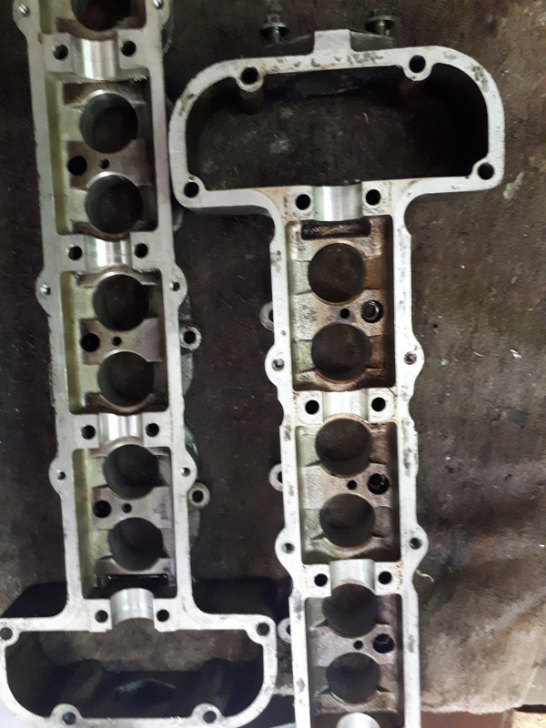
Reporting that this design, with nuts under the plate instead of threaded holes in the plate, is not suitable for preHE. Following photo, tappet block on the right is HE, flange has cut-outs above the head bolt locations that provide clearance for the nuts. On the left is my E-type tappet block, no cut-outs. I got away with it by swapping the tappet blocks. Otherwise worked well, dimensions were good.
Regards,
ColinL
'72 OTS manual V12
ColinL
'72 OTS manual V12
| Link: | |
| BBcode: | |
| HTML: | |
| Hide post links |