Hi,
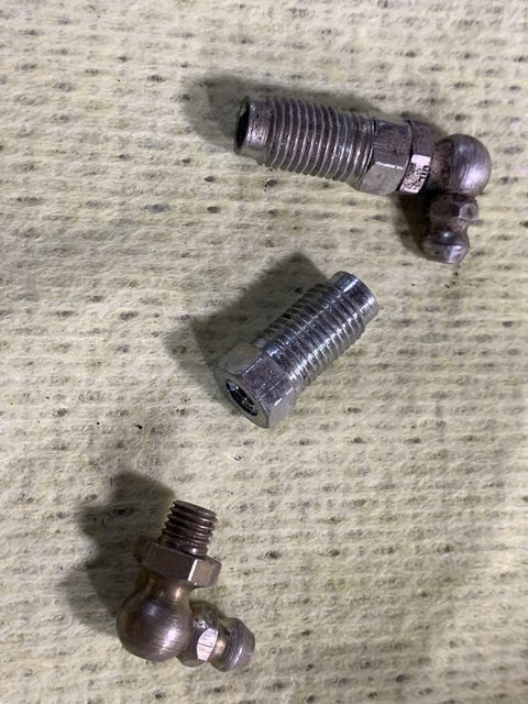
A really quick and easy grease gun/hydraulic adapter can be made with a brake line fitting nut and a grease nipple. I can’t remember the tap size but it might vary depending on the nipple anyway, normal brake line is 3/16”. However, it was just one from a normal grease point on the car, combined with the normal brake line fitting. I did not have to drill out, the existing hole took the tap and whilst it might not be a structurally sound job, it easily holds the pressure and I have dismantled some very old and cruddy hydraulic cylinders.
It’s not just a fluke of size, because I lost my first one, so made another which works just as well. Use a decent handheld grease gun and make sure the end is firmly and correctly fitted to the grease nipple.
All from my spares boxes, photo shows the two components plus one I made earlier.
Regards,
Simon.