


I cannot find out the layout of all the vacuum pipes on my series 3 V12. From what I can determine there are 3 items that use vacuum.
1. The distributor. I've taken a pipe from underneath the left hand rear carb to the distributor
2. The left hand air cleaner. Source and route unknown
3. The right hand air cleaner. Source and route unknown.
The service manual gives no information on this but the parts manual page 25 shows something from the exhaust manifold.
Can anybody help please.
Bob.
Vacuum Pipes on series 3


#2 Re: Vacuum Pipes on series 3
Hi Bob,
It does depend on the spec of your car, but assuming an early UK spec, the air cleaner vacuum pipes are there to control the temperature of the air entering the carbs during cold running, prior to the engine getting warm.
You need the temperature sensors in the filter housings to be working (new items are available and I got mine from SNGB), also there are two valves which move under vacuum to block the intake using internal hinged flaps in the intake trumpets, these also need to be functional - you can test by sucking them. The diaphragms can get damaged or the flaps can get distorted and jammed, it should be possible to free them. Mine were stuck with paint and slight distortion.
Air is taken from tappings on the inlet manifolds, which are fairly difficult to access as they are on the opposing faces of the manifolds, in the gap between the manifolds on either side. They are fairly visible but with the plumbing, linkages, etc it is tricky to fit the flexible vacuum tubing. The tubes then go into the temp sensors, connecting them to vacuum, which is used as a force to close flaps in the filter box intakes. The temperature sensors move (can’t remember if they open or close) with changes in temperature as the engine heats up. Eventually they allow or exclude vacuum into the valves on the filter housings to move them, opening or closing the flaps mentioned earlier. When the engine is cold, the flaps cause air to be drawn from around the manifold (warmer of course), when the engine warms up, they move and cooler air is drawn from the front of the engine bay through the trumpets. The warm air aids cold combustion and speeds engine warm up time, reducing time on choke, while the later, cooler air has greater mass flow and gives more power.
The parts catalogue was how I identified the tappings and routes, plus inspection of th car itself.
Other spec cars have more tappings and may have different manifolds accordingly.
There’s much debate whether they really help, but I decided to get mine working as a challenge and believe I have a quicker warm up period as a result. You can just block the manifold trappings instead - once the car is warm they have no purpose anymore and the engine does not like vacuum leaks. Arguably, the more vacuum devices and pipes you have, the more susceptible to leaks the car is and it becomes impossible to tune correctly.
Good luck, but remember to make sure there are no vacuum leaks.
Regards,
Simon
Last edited by vee12eman on Tue Jul 31, 2018 4:30 am, edited 1 time in total.
Regards,
Simon
Series III FHC
Simon
Series III FHC
| Link: | |
| BBcode: | |
| HTML: | |
| Hide post links |
#3 Re: Vacuum Pipes on series 3
Thanks for the info,
The engine in my series 3 is a hybrid. The original engine was destroyed, or so the previous owner told me, and an HE engine from an XJ was put in its place. I have had a lot of difficulties with converting it to the E-type. Sump, oil filter, carbs etc are different. It took time and it will now run and I have tuned it using a Gunson colourtune.
The only vacuum outlet I can find is underneath the left rear carb. I have used this to operate the advance/retard mechanism on the distributor. I have now got to the stage where I want to fit the air filters and cannot find a vacuum take off. Parts catalogue show a take off from the exhaust manifold. This is plugged on mine.
Is it strictly necessary to have these filters connected to the vacuum system?
Regards,
Bob
Bob.
| Link: | |
| BBcode: | |
| HTML: | |
| Hide post links |
#4 Re: Vacuum Pipes on series 3
Hi Bob,
In a word - no.
The engine ran fine for me for several months, without the temperature sensors and associated valves on the filter housings working, until I realised what it was all for and set about making it operate as original. I wanted a challenge to get the system working and although it seems to have improved warm up time and therefore economy, because I need the choke for less time, there is no need to get the system working if you don’t want to, I think the majority seem to be that way.
You mentioned a take off from the exhaust manifold, I take it you mean the inlet manifold? There should be one each side for the temperature/inlet system. I’ll have a look see if I have any photos when I get a chance.
Do make sure the take off points are all tightly blanked off however.
Regards,
Simon
Regards,
Simon
Series III FHC
Simon
Series III FHC
| Link: | |
| BBcode: | |
| HTML: | |
| Hide post links |

#5 Re: Vacuum Pipes on series 3
If the vacuum-unit of your HE distributor is a ADVANCE type, the hose must be connected to a drilling at the Stromberg, which is ending inside the carb "air-channel" roundabout 1 or 2 mm in FRONT of the butterfly of the carb. You can find information for this in the internet. Look for "tappered edge" and "advance unit".
Which types of carbs di you have ? Is your motor running ? Has you driven the car ? Is it driving okay ?
If you have another cabr, mayby the shape of the carb-needles are wrong. This can lead to a wrong mixture. Too lean or too weak. Weak in some areas of the "zero to full" and lean in another areas.
The shape of a carb needle must have a very exact shape , to fit to a certain motor. If you cahnge the exhaust system, the motor needs another needle profile, to have the correct mixture.
The problem will be, that you can find only few car mechanics, which are able to shape a needle for good "fitting". I have done it for my V12 eith a 6L motor and 4 original Stromberg carbs. It was a lot of reading, "grinding" 4 needles, testing them in the carbs while driving, reshape them , test again, reshape , test again and throw the in the dust bin.
Buying four new needles and start the process again,
If the needles of your carbs ar for out of "fitting", you need a lambda measuring system in the car, to test, how you taylor-made needles are "fitting".
Maybe you have luck and the existing needles are fitting "not bad" for the HE-Motor. If not, you will have BIG problems, that the motor is working well. It is NOT !!!!! possible to adjust the mixture of part or full throttle with turning a "srew" at the 4 carbs. The correct needle PROFILE determins the correct mixture. "Runs well" and a really correct mixture is different.
Most people and car-mechanics because of low brainpower are not able to understand this. They speak about "adjusting the mixtue" and other blahblah. Often such conversions are running bad, because of wrong mixture. The motors runs, but not good. You will be able to adjust the mixture at idle, if you lift the needle with the adjusting tool, but nearly NOT (!!!) at higher part or full throttle.
I have read a lot about this, thought a lot about this, have measured a lot with a LC-1 lambda measuring system from innovate while driving and grindet hours and hours 4 complete sets of needles, until the mixture was okay at idle, part throttle and full throttle.
I would be very interessted to read, if your motor is running well.
My motor has a advance unit for lower gas consumption at part throttle and the units in the air filter conected for quicker warm-up of the carbs and the inlet-system.
Regards Wolfgang Gatza
| Link: | |
| BBcode: | |
| HTML: | |
| Hide post links |


#6 Re: Vacuum Pipes on series 3
G'day Bob.
Check your distributor vacuum module. If the vacuum tube connects to the front (headlight side) of the distributor vacuum module you have a vacuum RETARD system. If it connects to the back it is a vacuum ADVANCE system. The vacuum source underneath the left hand rear carb is for a vacuum RETARD system, do not try and use the vacuum source underneath the left hand rear carb (seal it off) if your distributor is a vacuum advance system.
Check your distributor vacuum module. If the vacuum tube connects to the front (headlight side) of the distributor vacuum module you have a vacuum RETARD system. If it connects to the back it is a vacuum ADVANCE system. The vacuum source underneath the left hand rear carb is for a vacuum RETARD system, do not try and use the vacuum source underneath the left hand rear carb (seal it off) if your distributor is a vacuum advance system.
Regards,
ColinL
'72 OTS manual V12
ColinL
'72 OTS manual V12
| Link: | |
| BBcode: | |
| HTML: | |
| Hide post links |
#7 Re: Vacuum Pipes on series 3
Thank you for your help.
Wolfgandg, I found your information interesting but probably outside of my ability to carry out. I do not possess machinery that would be capable of grinding needles to that type of precision.
Wolfgandg, I found your information interesting but probably outside of my ability to carry out. I do not possess machinery that would be capable of grinding needles to that type of precision.
Bob.
| Link: | |
| BBcode: | |
| HTML: | |
| Hide post links |
#8 Re: Vacuum Pipes on series 3
Hi I came across this post and it is troubling me as I also have a hybrid HE engine, with stromberg carbs. Going by the posts here the distributor vacuum is at the back, I therefore would have the vacuum advance system. The vacuum tube from the distributor on my car is connected to the right hand inlet manifold and the vacuum source on the left hand inlet manifold is blanked off. Going by the below this seems to be wrong. Also I have found in the left air filter housing the temperature sensor has been removed and replaced by a small copper pipe. Currently this is connected to the connection at the front of the air trumpets. I am wondering if rather than drill an outlet near the carb butterfly the person who fitted the H.E. engine used the copper pipe in the air filter housing which is bent towards the carb air inlet in a similar way to suggested in Woolfi’s earlier post and for some reason this was changed at a latter date. What should be the consequences of having the distributor vacuum advance connected to the inlet manifold?
Regards
Dave
Regards
Dave
Dave
1972 S3 2+2 with HE V12
1972 S3 2+2 with HE V12
| Link: | |
| BBcode: | |
| HTML: | |
| Hide post links |
#9 Re: Vacuum Pipes on series 3
IF ( ? ? ? , you have to check this carefully !!! ) you have a advance unit, the advance unit is adding roundabout 16 or 24 degree of crank advance time to the pre-ignition at idle. You will have roundabout 16 or 24 degree of pre-ignition at idle, if the distributor is turned / fixed to zero degree of pre-ignition.
At idle, when the butterflies in the carbs are nearly closed, you have FULL amount of vaccuum. Therefore full amount of vaccuum pre-ignition with , if I am correct, 24 degree of pre-ignition.
If I remeber well, some "normal" advance units have 16 degree, the unit for the HE-motor has 24 degree.
I am wondering, how a HE-motor is working, if somebody who does not understand all this correct, is putting carbs, motor und ignition together and turns the ignition key.
Regards Wolfgang Gatza
| Link: | |
| BBcode: | |
| HTML: | |
| Hide post links |
#10 Re: Vacuum Pipes on series 3
Hello Dave, you appear to have a vacuum advance distributor. 1st thing to say is that your distributor connection is sort of ok for this. 2nd is a test for you to perform. 3rd is explanations:
The test: Take off your distributor cap so you can see the mechanism inside. Disconnect the vacuum tube to the distributor (from the manifold). Suck on it. Does the mechanism in the distributor move and hold when you suck? Yes = good. No = vacuum module is faulty (diaphragm has a hole in it). The consequence of a faulty distributor vacuum module is significantly reduced fuel economy. Otherwise not harmful. Does the mechanism snap back when you stop sucking? Yes = good, No = distributor is gummed-up, needs to be overhauled (important).
Explanations:
Vacuum is only available from the inlet manifold, caused by the engine always trying to suck air out of the manifold faster than the carburetor (throttles) allowing air into the manifold. There is no vacuum from the air filter housing or anywhere else, only from the inlet manifold. So, connecting yr distributor to the air filter housing would do nothing, yr vacuum advance would not work, consequence as above, lousy fuel economy.
On V12E’s vacuum is used for the following, explained in turn:
• Power assisted braking (no explanation)
• Distributor vacuum advance or retard
• Carburetor bypass valve activation
• Gulp valve activation
• Air inlet temperature control
Distributor vacuum advance or retard – for these the vacuum is mostly taken from the manifold close to one of the carburetor throttles (left-rear). These “throttle-edge tappings” are so the throttle can pass over the offtake and turn the vacuum on or off. If the take-off is underneath the carb there is vacuum when the car is idling and none when the car is driving. This is used for vacuum retard distributors (retard is only when idling). Most V12E’s had this originally. You have upgraded to vacuum advance, so the take-off under the carb should be sealed off (important).
If the take-off is from the top of the carb there is vacuum when the car is driving and none when the car is idling. This is used for vacuum advance distributors, i.e. what you should ideally use. Trouble is most V12E’s don’t have such a tapping (except some country specific cars). There are two solutions: either have a tapping installed by experts, i.e.: https://www.britishvacuumunit.com/ported-vacuum.html
Or simply connect to any convenient manifold vacuum take-off, that is well away from the carburetors. The disadvantages of this latter, of not using a “top-of-carb, throttle edge tapping”, is that there is vacuum advance when idling which may cause:
• Car idling speed may (?) be unstable and relatively rough;
• Yr car may (?) produce more pollutants when idling.
• The advance vs load may not be ideal, but better than nothing.
Carburetor bypass valve activation – vacuum lines from one of the (4, interconnected) manifolds connects to the 4 carb bypass valves, to pull the bypass valves open when engine braking (high vacuum) to reduce pollutants.
Gulp valve activation – vacuum line from one of the manifolds connects to the gulp valve, to pull the gulp valve open when engine braking (high vacuum) to prevent backfiring.
Air inlet temperature control - vacuum lines from each of two manifolds connects to flap valves in the two air inlet trumpets, via temperature sensors in the air inlet housings, to divert air that has been heated by the exhaust manifold, into the engine until it has warmed up. I.e. there should be vacuum lines from the maniflds to the temp sensors and from the temp sensors to the air trumpet flap valves. If here is no connection from the manifolds to the temp sensors, the flap valves are not being actuated, car will be a bit slower to warm up.
Regards,
ColinL
'72 OTS manual V12
ColinL
'72 OTS manual V12
| Link: | |
| BBcode: | |
| HTML: | |
| Hide post links |
#11 Re: Vacuum Pipes on series 3
Thanks Woolfi and Colin, this is very explanatory. The previous owner had the engine work done by Wolf Direct racing a few years prior to the various issues that the company went through before they went bust. I believe they were considered Jaguar V12 experts at the time. Rather than take off the distributor cap I squeezed the vacuum hose shut and the revs dropped at idle so I assume the advance in the distributor is doing it’s job. However, because it is effectively a hybrid engine and the HE engine did not have carbs I am learning all the time. For interest it has the lucas CEI ignition fitted as well.
Thanks for your help
Thanks for your help
Dave
1972 S3 2+2 with HE V12
1972 S3 2+2 with HE V12
| Link: | |
| BBcode: | |
| HTML: | |
| Hide post links |
#12 Re: Vacuum Pipes on series 3
The disadvantages of this latter, of not using a “top-of-carb, throttle edge tapping”, is that there is vacuum advance when idling which may cause:
• Car idling speed may (?) be unstable and relatively rough;
• Yr car may (?) produce more pollutants when idling.
• The advance vs load may not be ideal, but better than nothing.
In my car the previous owner has connected the advance vaccuum to the inlet manifold. The result was a preignition time of 26 degree idle. The idle was stumbling and the pollution was strong. When the micture in the cylinderhead is ignited 26 degree before TDC, sometimes the "mixture-cloud" is not dense enought, that it will ignited. If the spark is comming nearby TDC the mixture-cloude is pressed more and the chance to be ignited is higher. I fighted with this problem for three years, until I found, that the spark at idle was at roundabout 26 degree befor TDC.
Also the vaccuum is reducing, when opening the butterfly of the carb.
For a good matched curve of ignition time vs. amount of throttle, the rubber hose from the advance unit MUST !!!!!!!! be connected to the "tappedred edge" point in the carb. ALL other points of taking the vaccuum are wrong, to produce the correct curve of vaccuum for a well fitiing ignition time in relation to the amount of power.
If you check in google for "jaguar" "tappered edge" you can find articles, which explaine very clear with pictures of the drilling, where this "tappered edge" shall be located exatly in the Stromberg carb.
Regards Wolfgang Gatza
| Link: | |
| BBcode: | |
| HTML: | |
| Hide post links |
#13 Re: Vacuum Pipes on series 3
The use of "ported vacuum" as opposed to "manifold vacuum" is a separate topic.
The ported vacuum source will be the same as for the exhaust gas recirculation tapping on the later US cars, which comes out at the airbox side of the throttle plate and is visible from above just betweenn the carburettor and the manifold.
Tapping at this point has thre effect of supplying no vacuum advance at idle, but cutting in rapidly as the throttle is opened between 5-30%. At larger throttle openings, the ported vacuum signal then simply equals the manifold vacuum signal.
Arranging it this way has three effects:- firstly, it provides no vacuum signal at all at idle as the vacuum capsule sees atmospheric air pressure on one side and only airbox air pressure on the other, which with a closed throttle means the airbox and the outside world have not enough pressure difference to affect the capsule; secondly, it cuts in more or less instantaneously with an opening throttle, so the "off of the line" kick it gives when initially putting the foot down makes a big difference. Lastly, during overrun, when the car is coasting and the engine is unloaded with a closed throttle, it'll cut the vacuum advance again.
Above about 35% throttle opening, vacuum starts to taper off as the engine is starting to have delivered to it all of the air that the cylinders want - at wide open throttle there is no vacuum signal at all. At these throttle openings, ported vacuum and manifold vacuum are the same as each other and diminishing, so the advance delivered also diminishes as the throttle is held progressively held further open.
The total amount of advance supplied will be static advance at the distributor, centrifugal advance based on rpm and vacuum advance (or retard). The last of these, depending on the capsule type and the pipework may be capped, temperature dependent, provide retard or advance, but is only one component of advance system.
Some "performance" camshafts will have an uneven idle and leave a poor vacuum signal at low rpm. Adding advance at idle is one way to raise and smooth that out, so ported vacuum is not the universal panacaea it is made out to be.
Subject to not exceeding safe total amount of advance, it is one way of upping the advance curve in the lean cruise and off the line scenarios without upsetting idle quality.
kind regards
Marek
| Link: | |
| BBcode: | |
| HTML: | |
| Hide post links |
-
colin gray
- Posts: 47
- Joined: Wed Sep 12, 2012 8:13 pm
- Location: march cambs

#14 Re: Vacuum Pipes on series 3
I am about to fit a vacuum advance unit to my car (couple of weeks time) and note that currently the vacuum pipes for the distributor split into two then go to each side where they again split into two they, are then individually connected to the bypass valves on the carburettor sides.
Is this giving me manifold vacuum or otherwise? I note the general view is that ported vacuum is best practice. I also wonder how the bypass valve will be affected if I remove the distributor pipes and blank off the ports? So many blinking pipe they can not all be needed and how many ponies are they robbing my engine of???
Is this giving me manifold vacuum or otherwise? I note the general view is that ported vacuum is best practice. I also wonder how the bypass valve will be affected if I remove the distributor pipes and blank off the ports? So many blinking pipe they can not all be needed and how many ponies are they robbing my engine of???
| Link: | |
| BBcode: | |
| HTML: | |
| Hide post links |
#15 Re: Vacuum Pipes on series 3
Colin. Referring to my earlier post. There are 5 systems that use vacuum. 2 of these are the distributor and the carburetor bypass valves. Each of these needs to be sucked open by vacuum. From your explanation, you have these connected to each other and not to any vacuum source. So they won't be working. Makes me wonder, the vacuum take off points where these should be connected, have they been blanked off? If not you're losing a lot of Ponies. Get yourself a vacuum test gauge. Connected to the manifold instead of the brake vacuum hose, what is vacuum at idle?
Regards,
ColinL
'72 OTS manual V12
ColinL
'72 OTS manual V12
| Link: | |
| BBcode: | |
| HTML: | |
| Hide post links |

#16 Re: Vacuum Pipes on series 3
I had mentioned on other posts that I still have a retard unit. I have replaced these more than once due to diaphragm perforating. There's a lot of cheap replicas out there so keep a check on them. I had considered advance unit but don't have the tapping next to the butterfly so decided against it based on so many warnings that it must be so. Even with the retard it still takes a long time to warm up the 18 or so litres of coolant.
I have noticed that many sneaky professional restorers are using the six litre XJS engines. Does make some sense but not for me. Drove beautifully to Goodwood
I have noticed that many sneaky professional restorers are using the six litre XJS engines. Does make some sense but not for me. Drove beautifully to Goodwood
Adam
S3 V12 E Type FHC Manual 1972-owned since 1978
1957 XK150 since 1976
S3 V12 E Type FHC Manual 1972-owned since 1978
1957 XK150 since 1976
| Link: | |
| BBcode: | |
| HTML: | |
| Hide post links |

#17 Re: Vacuum Pipes on series 3
Hi Guys
Just an idea for some of you who don't have the ported vacuum carburettor with the port on the top for the vacuum advance module.
Quite a few other jags of similar vintage used the same carb with the correct advance porting, im thinking of the jaguar saloons XJ6 series, or some of the later V12's, early XJS.
With your abundant supplies of old jags a wrecker might be a good source of a suitable carb.
for some good pictures of the correct drilling go to
http://www.pclarkson.plus.com/
See the pages and pictures of Pauls story on modifying his carbs, and ignition, it really is an excellent discussion.
Cheers
Mark
Mark Brown
1971 S3 Etype, now sold, sadly.
1971 S3 Etype, now sold, sadly.
| Link: | |
| BBcode: | |
| HTML: | |
| Hide post links |
#18 Re: Vacuum Pipes on series 3
Hey Mark, inspired by yr earlier post i did this also.
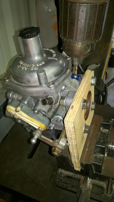
However such diy is only for us antipodeans, poms should contact https://www.britishvacuumunit.com/ported-vacuum.html
Only risk is the punishment they will inflict on themselves for not doing it earlier ...
However such diy is only for us antipodeans, poms should contact https://www.britishvacuumunit.com/ported-vacuum.html
Only risk is the punishment they will inflict on themselves for not doing it earlier ...
Last edited by lowact on Mon Jul 30, 2018 5:00 am, edited 2 times in total.
Regards,
ColinL
'72 OTS manual V12
ColinL
'72 OTS manual V12
| Link: | |
| BBcode: | |
| HTML: | |
| Hide post links |
#19 Re: Vacuum Pipes on series 3
Good on yer cobber, how did it go?
Mark Brown
1971 S3 Etype, now sold, sadly.
1971 S3 Etype, now sold, sadly.
| Link: | |
| BBcode: | |
| HTML: | |
| Hide post links |
#20 Re: Vacuum Pipes on series 3
Nbg. Carb is ok but haven't fitted my vacuum advance distributor yet. Discovered I have low vacuum at idle for no external reason. Pointless doing anything to the ignition until I can cure this ...
Regards,
ColinL
'72 OTS manual V12
ColinL
'72 OTS manual V12
| Link: | |
| BBcode: | |
| HTML: | |
| Hide post links |