288gto wrote: ↑Tue Mar 10, 2020 11:53 am
andrewh wrote: ↑Tue Mar 10, 2020 8:15 am
Lets hope the manufacturer has a satisfactory answer.......... To me
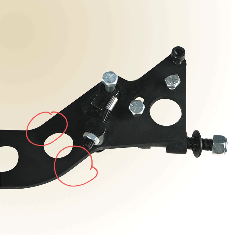
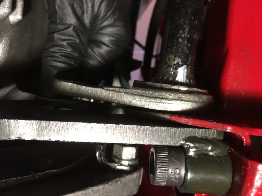
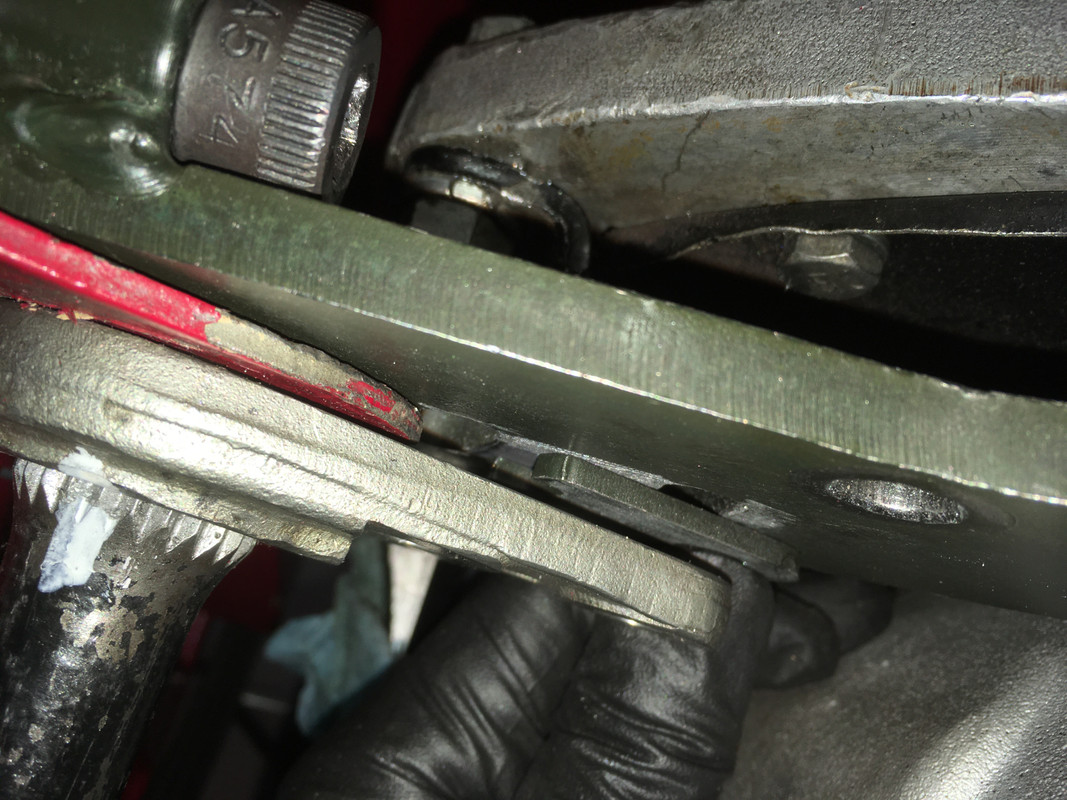
the basic design is flawed as mentioned above, the 5/16 bolt is taking the strain that should be carried by the Reaction plate which appears not upto the job.
Which is not helped I suspect Andrew by the large, presumably "lightening", hole in the reaction plate near to where the load is being transferred.
I think we're getting bit ahead of ourselves, chaps. We’re abandoning logic here in and it doesn’t do Keith any favours to reflexively circle wagons and take pot shots at vendors.
It can, and does, often require mountains of data to prove something conclusively, whereas a single confirmed observation can cause even the most persuasive theory to come crashing down, which is what seems to be the case here, herd mentality notwithstanding.
A few years ago I had the pleasure of spending time with Jason Len, hardcore motorcyclist and founder of XKs. I drooled all over his Lightweight racer that was in the shop and used many/most of XK’s performance goodies, including the adjustable reaction plate.
As anyone who has raced learns on Day One, the loads imposed on a car during hard track running far outweigh those encountered during street driving. This would be true using identical cars, but applies much more when the track car is far quicker and has massive sticky tyres, hard suspension and someone quick behind the wheel. Any suspension component that failed due to bad design after only 200 miles of road use would fail far more quickly on track. Meanwhile, one would expect that an inherently badly-designed component which failed at 200 miles might occasionally fail at lower mileages, sometimes at similar mileage and more often after greater mileages of, say, 1,000 miles or more. Such a situation would not escape the notice of the maker and/or seller.
I have no dog in this fight and have fitted a Rob Beere plate to the D, since it is obvious in advance that Jaguar’s E-type settings will not apply to an aluminium car and probably several adjustments will be needed once I install the engine. But logic is logic and statements that a design is flawed, even written in bold type, do not make sense at this stage, or possibly ever. I do accept that theoretically one design may perform as well as any other once fitted, but may encounter a higher failure rate in practice, due to a greater likelihood of incorrect fitting. Which is not to say that’s what has happened here, yet.
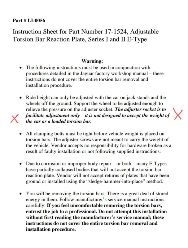
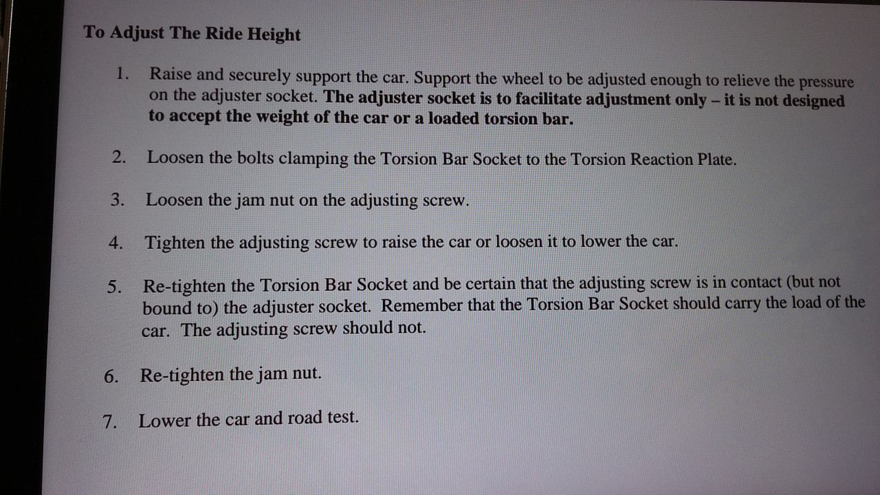
I haven’t seen the XK instructions (perhaps Keith can show them here?) but I imagine that the threaded adjusters are used to vary the position of the bars at full droop, before the torsion bar brackets are secured tightly by 3/8 bolts in shear, as per normal. It looks to me self-evident that the adjusters have been subjected to compression/bending loads far in excess of what they were designed for, and as the pressure point is well ‘outboard’ the plane of the reaction plate, this has resulted in a twisting/bending moment the components were never designed to sustain. The most obvious cause for that would be improper assembly/tightening of the various parts, so that forces intended for the plate are borne by the adjusters.
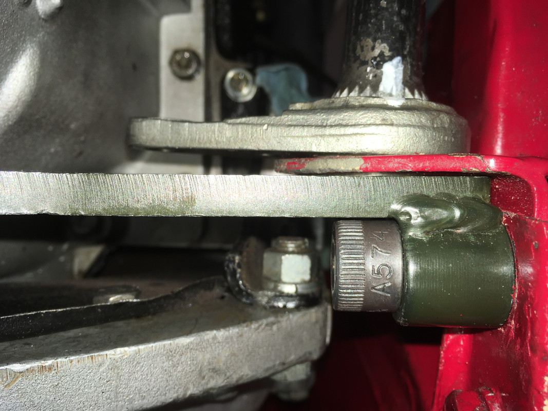
The Beere reaction plate cannot generate such loads because the TB brackets operate in almost pure shear at the face of the plate, as per the standard parts which also pass through the frame ears. The Beere plate needs a big Allen key and is perhaps easier to set unevenly side-to-side because it can be hard to count the flats at the low end of the range. But even if things aren’t tightened fully, or washers are omitted etc., there is unlikely to be much harm done because there remains little possibility of inducing bending or distorting forces. A badly-installed Beere version might therefore survive abuse longer than a badly-installed XKs version, perhaps with some washers or spacers transposed, yet both types perform equally well once correctly fitted.
I’m no engineer, but critical thinking and basic logic are no respecters of tertiary education. The flawed design hypothesis seems not to survive the real world failure rate test - this being the first we've heard of it - which leaves only the following:
A: Sound design, poor quality execution (incorrect material batch? Poor process control?)
B: Sound design, poor application (assembly issues, car structure issues?)
C: Sound design, good QC and application, but extreme environment (rallycross, bus jumping?

)
If option B were more common than with other designs, it could be regarded as a ‘flaw’, but that would be like damning all Series 1 cooling systems or con-rod split pins, even though the problems occur from misuse years later. The scenarios I can imagine are that the adjusters were overloaded by forcing the TBs under load rather than full droop, or at nearly full droop but still with dampers connected, or that the TB brackets were not secured fully once positioned correctly by the adjusters, or a combination of both. The f
first two hopefully unlikely, since if they were enough to bend the adjusters it would happen as they were being extended and would be obvious to Keith as he worked.
The strange angles and odd gaps are probably as much the result of the damage rather than cause, although threads don't usually undo under load, things just strip or snap. Not actually having seen the instructions also means we can't be sure. But my suspicion is that things went pear-shaped when the brackets pressed against the adjuster in use, instead of being tight on the reaction plate and loading that up instead. We know the bracket can sustain race-level heavy loads in the intended plane, but were have no comparator for lateral bending loads.