Page 1 of 1
#1 cooling fan power
Posted: Mon Jul 17, 2017 8:55 pm
by Grant
HI All Again.
1969 Series 2 USA OTS
Im working my way round the things that do not work and Ive come to the cooling fans which do not work.
I have applied power to the separately and they both work fine.
I have put a meter on each of the 2 wires both sides and it seems the left hand wire on both is the earth and there is no power.
So my question is Where is the power coming from ?
what colour do we think it is ?
and what else would i be supplying? so I can try and trace back where the fault has started ,
Also does the switch in the top of the radiator earth them or supply power ?.thank you
Also can anyone tell me what this is in the photo below? as you can see its position on a cross member just behind the cooling fans so could it be to do with them ?
once again I thank anyone for taking the time to read this and share their knowledge .
Regards
Grant.

#2 Re: cooling fan power
Posted: Tue Jul 18, 2017 7:27 am
by Gfhug
Grant, have you got a copy of the workshop manual (not the Haynes version) with the full description of the electrical systems and wiring diagrams? Also the knowledge section has wiring diagrams for all models with the colours to each wire. You'll find them invaluable in tracing which wire goes to which system.
Without them you'll find it very difficult to trace problems.
One of the issues with the radiator fans is the Otter Switch in the radiator. If this is faulty then it sends no signal to switch the fans on. Try to trace back from that switch near the radiator cap to follow the wires to your fans.
Geoff
#3 Re: cooling fan power
Posted: Tue Jul 18, 2017 8:43 am
by Grant
Hi Geoff,
I only have the haines manuel but I will try and get the other one.
I have now found the wiring diagram in the Knowledge section so will have another look at it tonight .
I have I identified the boxes behind the fans as relays but not sure yet if its the fan relay or horn relay?
I will check that tonight also ,but Im getting there .
Thanks for your reply
Grant.
#4 Re: cooling fan power
Posted: Tue Jul 18, 2017 10:51 am
by Gfhug
Grant, this is the book:
Available from the JEC, too and if you're not a member when you join your first purchases get a discount. They'll have the drivers handbook, too, and give valuations and other valuable services. The JDC can be useful too.
See how you get on with tracing the wires and report back.
Geoff
#5 Re: cooling fan power
Posted: Tue Jul 18, 2017 11:11 am
by mark10337
Horn relay is normally mounted on the left hand (nearside) mudshield.
The green wire will supply 12v to the motor from the fan relay that is normally mounted on the top of the cross member in front of the engine.
The relay is activated by the otto switch on the radiator. If you disconnect the wire going from the relay to the otto switch, and just touch it to a ground point, with the ignition on, the fans should come on.
#6 Re: cooling fan power
Posted: Tue Jul 18, 2017 2:57 pm
by Hugo
Grant wrote:
I have I identified the boxes behind the fans as relays but not sure yet if its the fan relay or horn relay?
Grant.
Pull one of the wires off & see if the horns still work - then you'll know

#7 Re: cooling fan power
Posted: Tue Jul 18, 2017 5:00 pm
by chrisvine
Grant,
Just a couple of observations, you mention the left terminal appears to be earth. The polarity on these DC series motors doesn't actually matter as the reversal of the current in the field coil is cancelled out by the reversal in the armature.
If your reading has confirmed a good earth connection on the left terminals then Mark's advice should enable you to determine if it's the relay in your photo that is at fault or the otter switch in the radiator. It might be a good idea to flip the relay over so the terminals are at the bottom. As it's currently orientated, you're likely to get water ingress as water is able to pool on the terminal plate. It's possible this could be the cause of your troubles.
Chris
#8 Re: cooling fan power
Posted: Tue Jul 18, 2017 5:25 pm
by Grant
Hi Mark , Hugo ,Chris
thank you again for your very informative answers,
I have followed all 3 and still can make the buggers work!
It goes like this
Firstly I have now swapped it with the horn relay which worked the horn but does not work the fans still.
I have power to the green
I have attached the red and black that goes to the otter to an earth nothing.
I have shorted the +Green straight to the fan supplies Green black and they work (should they work? as they are obviously earthed)
its only when using the relay they do not work but I've used 2 relays and the other worked the horn ok.
so whats not letting the relay work ? or in a different way what makes the relay work ?
something must trigger the connection between C1 and C2 but i can't get my head round what .
thank you again for any ideas.
Grant.
#9 Re: cooling fan power
Posted: Tue Jul 18, 2017 5:51 pm
by chrisvine
Grant,
The fact that the fans work when supplied directly with the green wire, normally connected to the C2 terminal, and they do not when the Black/Red is earthed would suggest it's the relay that is faulty.
The 6RA relays are not all the same so you'll need to add an additional jump lead if you're using the horn relay to fault find. The fan relay only has three terminals while the horn has the normal four terminals.
Below are the terminal connnections and internal wiring:
Alternator Relay – 33209F (SRB121) : 20A 4 pin
Starter Solenoid Relay – 33231E (SRB400) : double contact 5 pin
Cooling Fan Relay – 33232E (SRB501) : 3 pin
Horn Relay – 33252E (SRB111) : 20A 4 pin
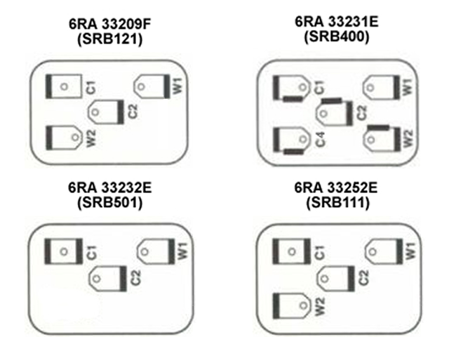
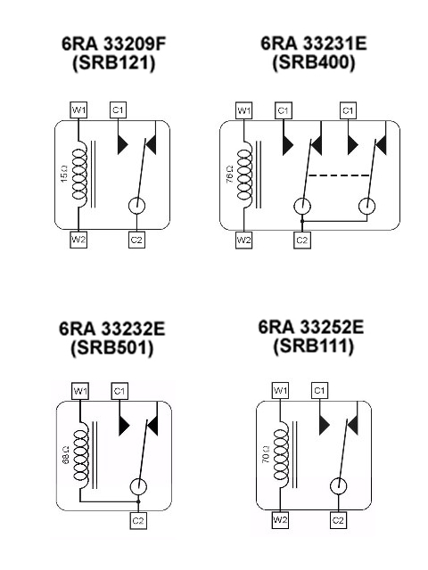
As you can see, the W2 terminal is dropped as the coil is connected directly to the C2 terminal. Therefore you'll need a jumper wire to connect the W2 & C2 terminals on your horn relay.
Chris
Ps you still might need to verify the otter switch works once you have them running with the Black/Red wire earthed
#10 Re: cooling fan power
Posted: Tue Jul 18, 2017 5:54 pm
by Hugo
I'm not familiar with the E Type set up, but I would be prepared to bet that there are two live feeds to the horn relay; one of which goes to earth when you press the horn button, and the other which feeds the horns when the relay is closed. The contacts that operate the relay are W1 and W2; the terminals that pass the feed across to the horns are C1 and C2. So I'm guessing that W1 and C1 are both live when the ign is on, and that W2 goes to ground via the horn button and C2 goes to the horns.
I believe there are also two live feeds to the fan relay; one to operate the relay itself when the Otter switch closes the ground circuit; the other to feed the fans themselves when the relay is closed. The terminals follow the same pattern; W1 is a live feed; W2 goes to the Otter switch; C1 is also a live feed, and C2 goes to the fans. European relays are marked with stupid numbers instead that mean nothing to any rational mind.
In other words, each relay should have two live feeds when the ign is on.
Don't take this as gospel, but I'd be prepared to bet a small amount of money that this is how they are wired.
Try closing each relay manually by means of a paper clip across W1 and W2 with the ign on. Pull one of the C wires off first and you should get a nice click off each relay. If you do, reconnect the C wire and try it again; you should get the horns and the fans respectively.
If you don't get a click, you are missing either the feed to W1, or the ground via the horn button or Otter switch.
Flash a jump wire from the battery pos (again assuming you're neg earth) briefly to C2 and you should get either the fans or the horn, or a bloody great flash if you have a short circuit.
#11 Re: cooling fan power
Posted: Tue Jul 18, 2017 6:47 pm
by mark10337
I'll take that bet Hugo
There is in fact only 1 live feed on C2. You can see this on the wiring diagram and the diagram of the relay above - 6RA 33232E (SB501). It links internally within the relay to the switch feed and the fan feed.
So first - ignition on, and see if there is 12V at C2. If not - Check fuse 7.
Next ground W1, and you should hear a re-assuring click, and have 12v on C1. If you don't, the relay is damaged.
If you get 12v on C1 and the fans are connected, check the wire from the relay to the fans.
#12 Re: cooling fan power
Posted: Tue Jul 18, 2017 7:14 pm
by Hugo
I was close - that's why I said a small amount of money
#13 Re: cooling fan power
Posted: Tue Jul 18, 2017 7:32 pm
by Grant
Hi Chris
You did it !
the funny thing is that this is how it was so its has obviously Never worked !
as there was the same relay for both horn and fan so it never had another positive to the W2 so could never have worked !!!
This of course is the fun and games of working on old cars, but what makes it more interesting is when I spoke to SNG Barret at 4pm they told me it the same relay for both horn and fan which is why I thought to try swapping them and hey presto the horn still worked on what was the fan relay which is why I was reluctant to think it was that, they never mentioned (or knew) that you needed the extra few to the W2.
so thank you very much for that.
And to you Hugo your answer made sense too.
1 more question.
Has anyone bought a correct 2 pin Relay recently and from where ?

Thanks again everybody
Grant
#14 Re: cooling fan power
Posted: Tue Jul 18, 2017 7:50 pm
by Hugo
2 pin relay? What's that?
#15 Re: cooling fan power
Posted: Tue Jul 18, 2017 8:18 pm
by Grant
Hi Hugo
sorry that was a typo its 3 pin as per Chris's answer
Cooling Fan Relay – 33232E (SRB501) : 3 pin
Thank you
Grant.
#16 Re: cooling fan power
Posted: Tue Jul 18, 2017 8:37 pm
by Hugo
I have a similar thing on my 1960 Impala in Florida - it uses a three terminal relay for the horn, but I just re-wired it for a modern four terminal relay. I think they ran both terminals to ground, if I recall correctly, so I just earthed each one separately. Four inches of wire & a couple of crimp-on terminals - not worth messing around trying to find a 3 pin.
#17 Re: cooling fan power
Posted: Tue Jul 18, 2017 9:21 pm
by Grant
hi Hugo
this actually links the positives but i get the gist of it, i will give it a try tomorrow,
thanks again
grant