Page 1 of 1

#1 Lucas DL3 Wiper Motor Wiring diagram and advice

Posted: Fri Nov 10, 2017 12:17 am
by wilkinsi
I am having problems renewing the wiring on my old DL3 as the original wiring disintegrated upon removal and I seem to remember that there was a wiring diagram posted but cannot locate it so any guidance would be appreciated.
Also it seems to be common practice to bypass the thermal cutout but does it in fact serve a useful purpose? On my motor the cutout points are in reasonable shape but the thermal strip has deteriorated so any suggestions as to the best material to replace it with?
Any thoughts greatly appreciated.

Cheers
Ian Wilkins
62 FHC 886763
Melbourne Australia

#2 Re: Lucas DL3 Wiper Motor Wiring diagram and advice

Posted: Fri Nov 10, 2017 2:13 am
by abowie
Image

Note that this wiper is wired for RHD.
The chances of the thermal cutout being useful are slim an you're never going to use the wipers anyway :bigrin:
I buy the wire online from Autosparks in the UK. Get the thinnest cloth wrapped one they sell. They also sell bullet connectors (ali ones are better than brass) and the tool for installing them.

#3 Re: Lucas DL3 Wiper Motor Wiring diagram and advice

Posted: Fri Nov 10, 2017 6:43 am
by wilkinsi
Thanks Andrew - that was just what I was looking for!

Cheers
Ian

#4 Re: Lucas DL3 Wiper Motor Wiring diagram and advice

Posted: Fri Nov 10, 2017 6:43 am
by wilkinsi
Thanks Andrew - that was just what I was looking for!

Cheers
Ian

#5 Re: Lucas DL3 Wiper Motor Wiring diagram and advice

Posted: Fri Nov 10, 2017 7:28 am
by JagWaugh
Just as an aside. Get a roll of Kapton tape at an electronics supply place. It's great for adding a tough thin layer of insulation in an area where a wire may rub on a surface (like the White/Green and Brown/Green wires in that picture).

#6 Re: Lucas DL3 Wiper Motor Wiring diagram and advice

Posted: Sat Nov 11, 2017 2:41 am
by wilkinsi
Thanks - good advice which I will follow

Ian
886763
Melbourne, Australia

#7 Re: Lucas DL3 Wiper Motor Wiring diagram and advice

Posted: Sat Nov 11, 2017 6:14 pm
by neal herridge
Andrew.
Could you tell me the colour of the wire going to the upper brush holder in the picture.
Also for a RHD car should the crank on the motor rotate anti clockwise.
Many thanks Neal.

#8 Re: Lucas DL3 Wiper Motor Wiring diagram and advice

Posted: Sat Nov 11, 2017 9:24 pm
by abowie
Blue wire.
When wired correctly, a RHD motor will be turning the spindle anti-clockwise (viewed from the spindle side).

#9 Re: Lucas DL3 Wiper Motor Wiring diagram and advice

Posted: Sun Nov 12, 2017 9:06 am
by Series1 Stu
Hi Ian

The thermal cutout is supposed to serve a useful purpose, that's why it's there. It is supposed to protect the motor from over heating and burning out it's windings. You should find one fitted to every wound motor in every vehicle, appliance or anything else so equipped.

It is not possible for you to successfully replace the bimetal strip as it is a precision calibrated device produced on tooling designed to give a precise operating temperature within very tight tolerances.

You are unlikely to be able to buy the cutout as it is probably long out of production. I suspect it was made by Otter Controls who made all of the cutouts used on virtually every British car of the era, including the well renowned Otter switch found in the cooling system header tank.

You may be able to swap the cutout for one from another motor - any protection is better than no protection.

Andrew - Ian lives in Melbourne. Of course he'll need his wipers. :lol:

Regards

#10 Re: Lucas DL3 Wiper Motor Wiring diagram and advice

Posted: Sun Nov 12, 2017 5:13 pm
by neal herridge
Many thanks Andrew.
Neal.

#11 Re: Lucas DL3 Wiper Motor Wiring diagram and advice

Posted: Fri Jan 10, 2020 9:27 pm
by rfs1957
I thought it made more sense to add these observations to an existing post rather than start a new one.

The cable-colours were inconsistent on my ex-USA Series 1 where the loom joins the 5-wire wiper-motor, plus I suspected it was running the wrong way round, so I had it apart and discovered a few horrors in the process.

Forum members will be reassured that they were apparently carried out by "the trade" in the UK around 30 years ago, if the PO's brochure is to be believed.

Image

Image

I make no pretence at being an authority on any of this, but - as usual with my postings - just feel that sometimes it is better to have some information and a few leads rather than none at all, and I would have felt more confident myself had I been able to see these pictures and read this account before I started.

Image

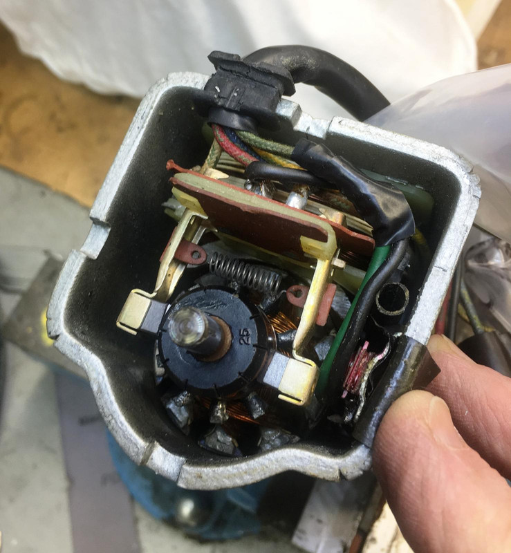
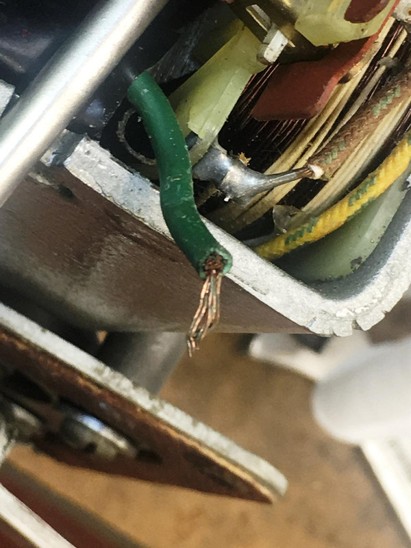
The innocuous bits of insulating tape revealed this, which was a pity because all the rest did indeed look brand new - right parts, wrong people doing the work.

Image

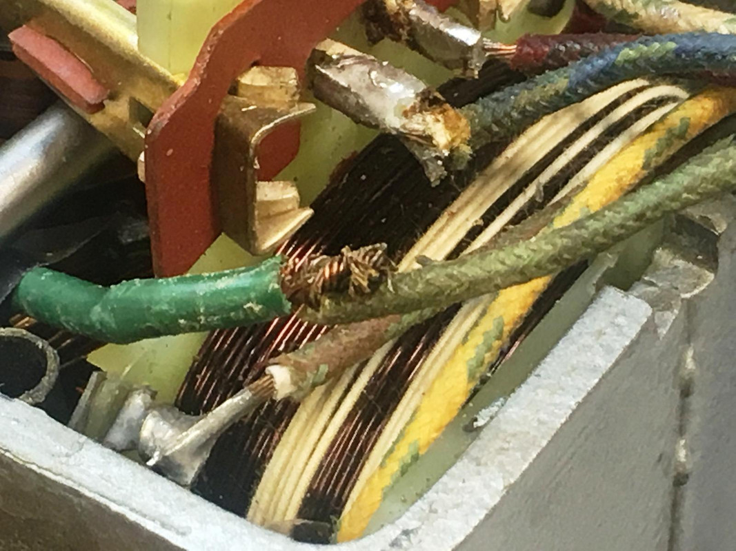
And things then got worse.

Image

Image

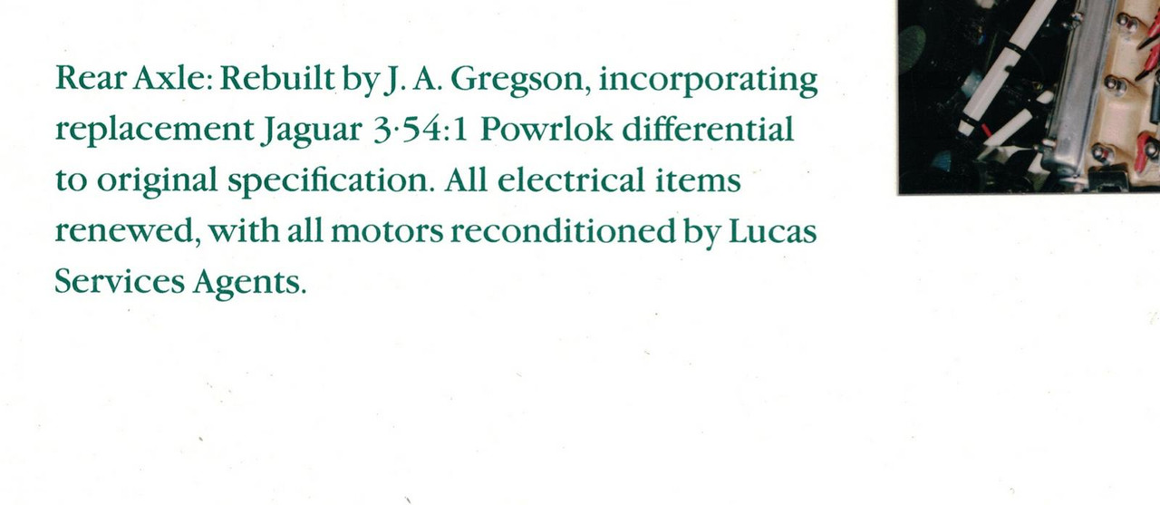
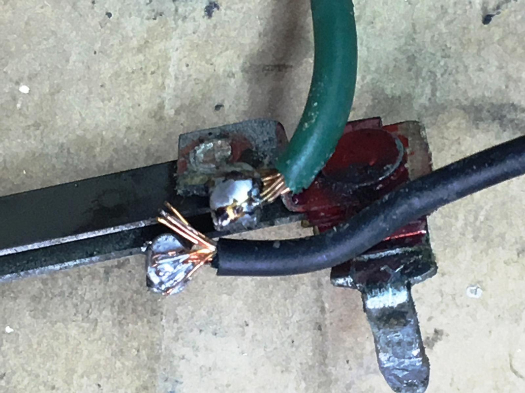
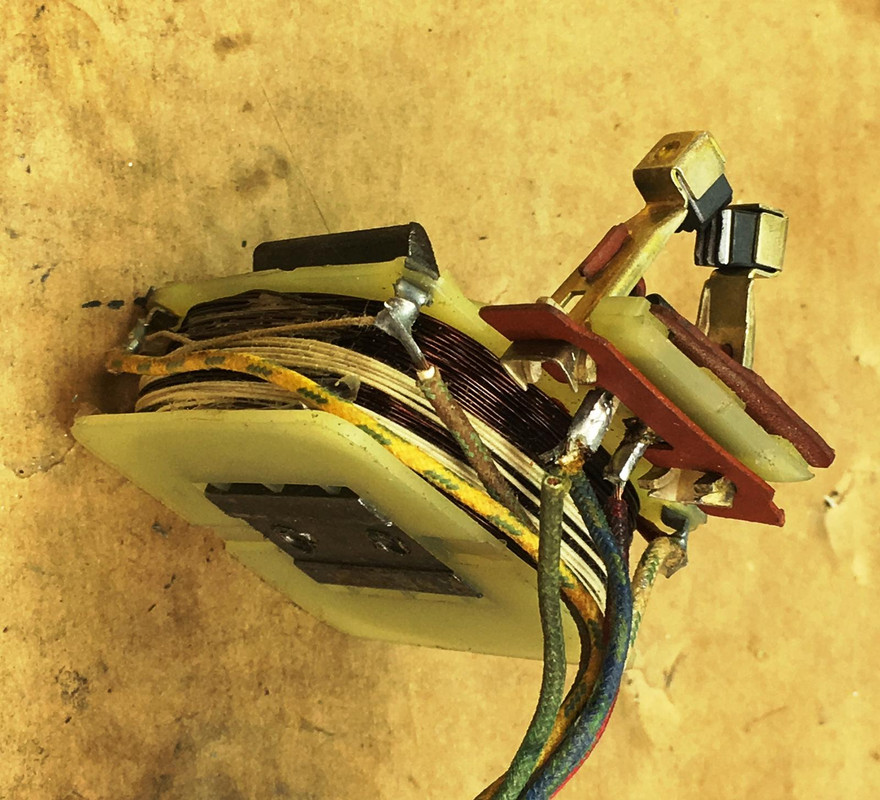
The tabs seen above are from the thermal-overload protection that not all motors have, apparently - the wiring to and from this was a total botch,

Image

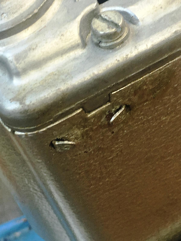
so I dismantled the casing and coils by removing the two nasty self-tappers (with weedy bizarre hex heads that rounded off at the slightest torque) - this is really easy and makes access to the wiring connections much easier than doing rotaional-direction swaps in-situ.

Image

The thermal-switch comes out once its tabs are released,

Image

it's easier to re-wire out of the casing.

Image

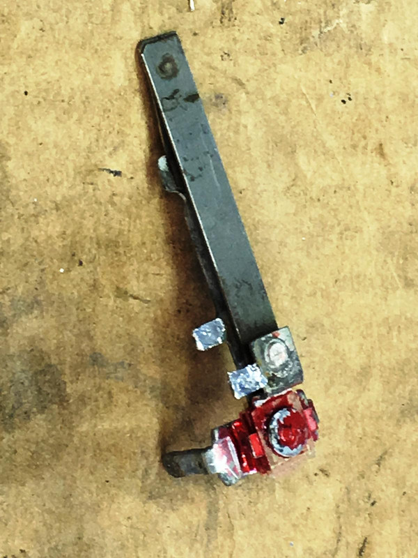
I replaced the fritzed backing insulation with a suitably ridged (so stiffened) strip cut from an oil can.

Image

Image

Image

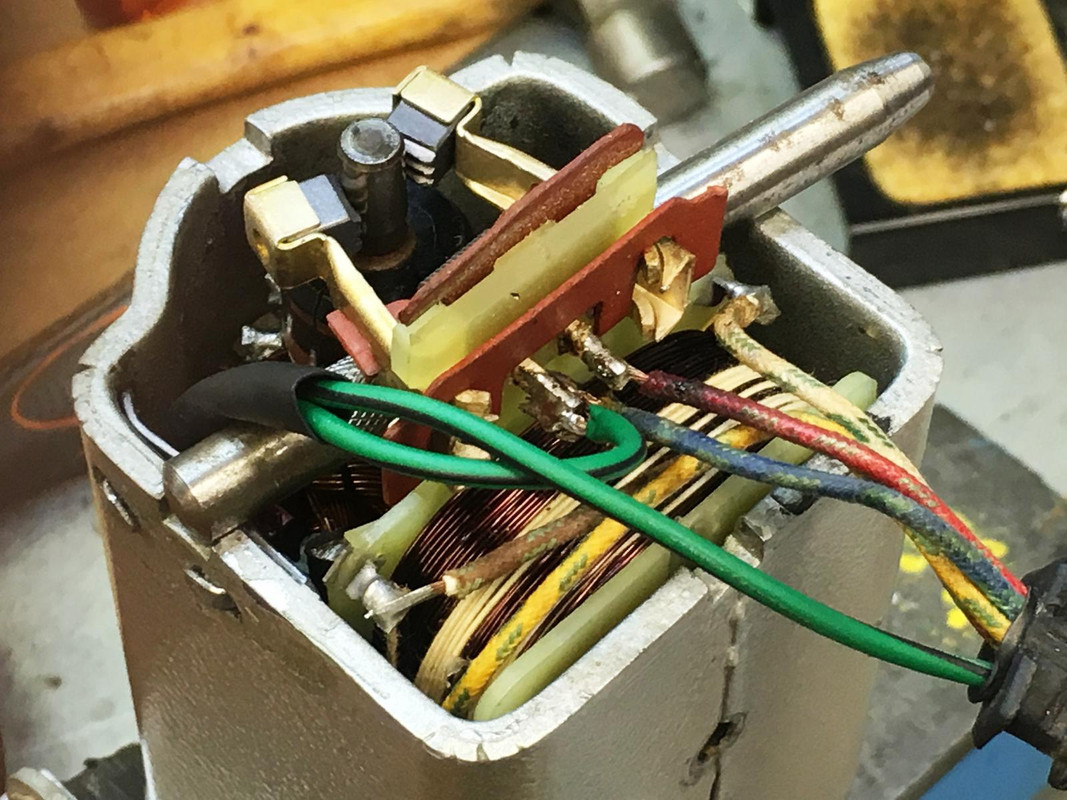
All this can be done without disturbing the motor armature and the driving mechanism in the gear case.

Image

Note that the guts were brand new still, down to the brushes still having their running-in ridges apparent.

Image

If you don't want to strip the motor completely, it's possible to just coax the coils and wiring board upwards and hold them proud with a bit of bar while you swap wires around, with good access.

Image

I found this article in the Knowledge base very helpful

http://www.xkedata.com/resources/read/?id=9

regarding the wiper-motor and its wiring, direction of rotation etc

Image

This wiring diagram is taken from this erudite analysis in the Knowledge Base, and shows clearly why you can't reverse the motor by just inverting two cables on the outside.

https://www.dropbox.com/s/x7f9u2g650up8 ... l.pdf?dl=1

Anyone wanting to know more about how the reversing and parking functions work, and why motor-rotation direction is so critical, could do worse than read this thread.

viewtopic.php?f=3&t=15113

#12 Re: Lucas DL3 Wiper Motor Wiring diagram and advice

Posted: Fri Jan 10, 2020 10:18 pm
by cactusman
For those that have a broken cut out an option would be to fit a 10 amp thermal fuse. 72set C is the lowest commonly available temp. It is not an ideal solution as the fuse is non resettable so if it fails you will have to disassemble and replace.....but you will probably need to do that anyway if the thing trips!

#13 Re: Lucas DL3 Wiper Motor Wiring diagram and advice

Posted: Fri Feb 26, 2021 3:44 pm
by GarryIno
Hi...I'm in a similar circumstance and furthermore have experienced a mental blackout on the shades of the wiper engine wires. The graph presented above appears to be just on have 5 wires so that can not be correct.

A photograph or 2 would be incredible in the event that anybody has something from inside the wiper.
order pcb