


Differential case side bearings
-
 lowact
Topic author - Posts: 760
- Joined: Mon Oct 09, 2017 10:05 am
- Location: Canberra, Australia
- Contact:

#1 Differential case side bearings
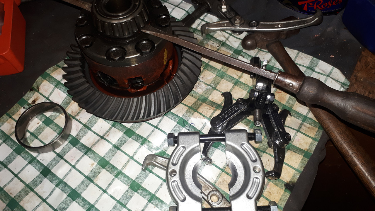
Anyone got a clever way to remove the diff side bearing cones?
Regards,
ColinL
'72 OTS manual V12
ColinL
'72 OTS manual V12
| Link: | |
| BBcode: | |
| HTML: | |
| Hide post links |


#2 Re: Differential case side bearings
Think you will need a "Clamshell" puller.....Steve
Steve
69 S2 2+2 (sold) ..Realm C type replica, 1960 xk150fhc
69 S2 2+2 (sold) ..Realm C type replica, 1960 xk150fhc
| Link: | |
| BBcode: | |
| HTML: | |
| Hide post links |
-
lowact
Topic author - Posts: 760
- Joined: Mon Oct 09, 2017 10:05 am
- Location: Canberra, Australia
- Contact:
#3 Re: Differential case side bearings
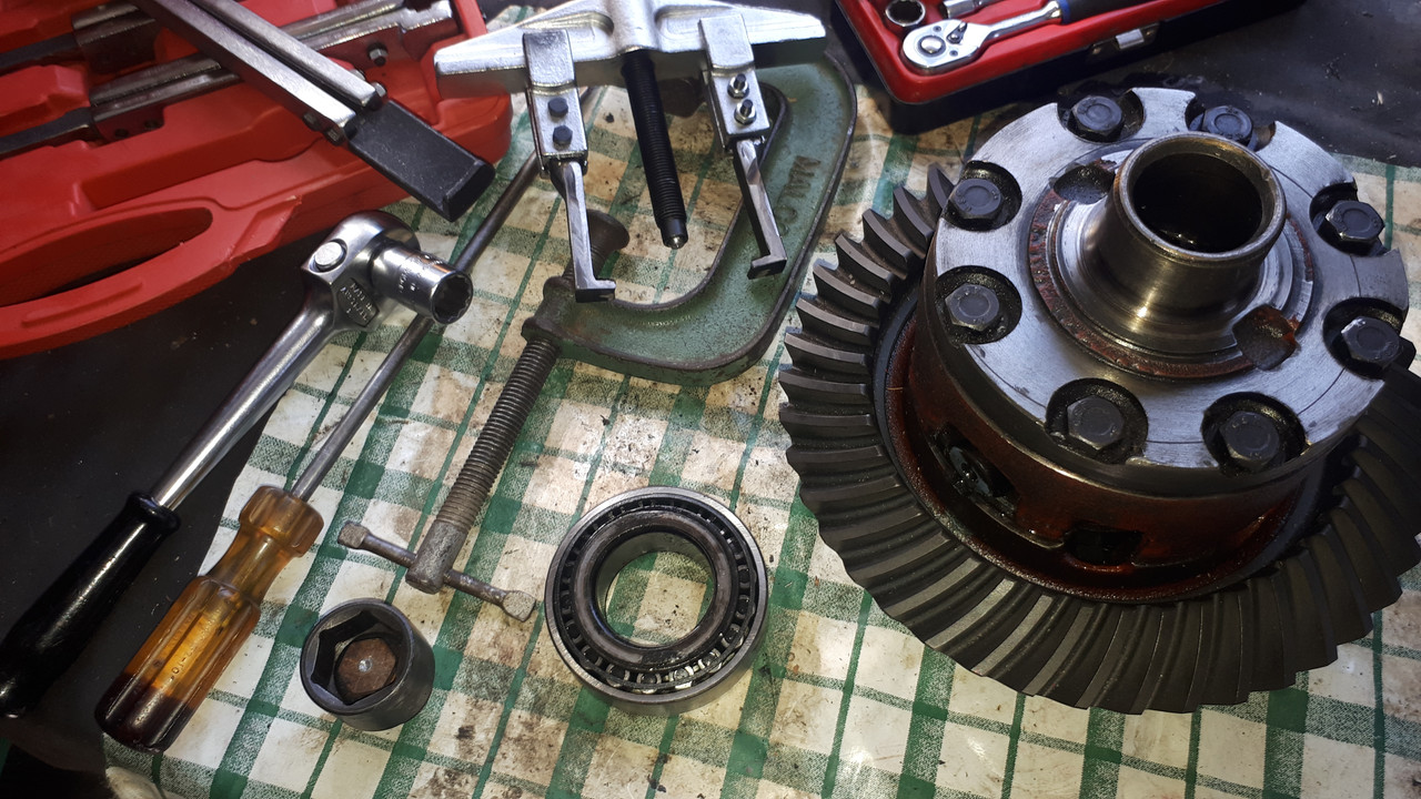
Maybe not. The bearing cones (with shims under) press hard against the side of the differential, there is zero circumferential gap for a clamshell. There are recesses for a 2 jaw puller i.e.:
To fit in the recesses the puller hooks need to be flat, narrow and max 5 mm thick so I reckon the steel would need to be very high tensile, haven’t found anything that inspires confidence, maybe this one, I would have to grind it to fit and the jacking screw looks a bit like a toy. If no better suggestions I’ll give it a go.
https://www.ebay.com.au/itm/284366860452
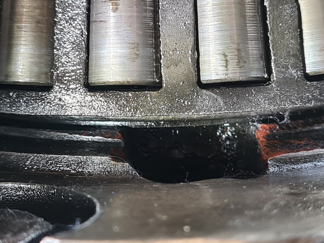
The pull will be against the underside of the shims, so I expect the shims will be damaged in the process. I’m tempted to just leave/reuse the bearing cones. But one of the bearing cups is damaged (displayed in the above pic), this will be due to the old oil seals having failed allowing all the diff oil to leak out. So sensible approach is new brgs all round, damit.
To fit in the recesses the puller hooks need to be flat, narrow and max 5 mm thick so I reckon the steel would need to be very high tensile, haven’t found anything that inspires confidence, maybe this one, I would have to grind it to fit and the jacking screw looks a bit like a toy. If no better suggestions I’ll give it a go.
https://www.ebay.com.au/itm/284366860452
The pull will be against the underside of the shims, so I expect the shims will be damaged in the process. I’m tempted to just leave/reuse the bearing cones. But one of the bearing cups is damaged (displayed in the above pic), this will be due to the old oil seals having failed allowing all the diff oil to leak out. So sensible approach is new brgs all round, damit.
Regards,
ColinL
'72 OTS manual V12
ColinL
'72 OTS manual V12
| Link: | |
| BBcode: | |
| HTML: | |
| Hide post links |
#4 Re: Differential case side bearings
Hi Colin.....the shims should be against the inner race.....the clamshell lips under the outer race...the problem here is reassembly and setting up the shims....ideally you want a dummy bearing or old bearing with its inner slightly reamed out......as you will need to install the unit measure and shim as required. ....if you "new" bearing has been pressed on you will then need to pull it to adjust shims....have a look at the diagram of the Jaguar puller in the S3 service manual......Steve
Steve
69 S2 2+2 (sold) ..Realm C type replica, 1960 xk150fhc
69 S2 2+2 (sold) ..Realm C type replica, 1960 xk150fhc
| Link: | |
| BBcode: | |
| HTML: | |
| Hide post links |
#5 Re: Differential case side bearings
Brutal I know but you could just cut it off with a grinder.
If you take the cage and rollers off might you get a clamshell onto it?
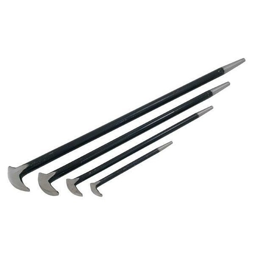
Edit. Looking at the cutouts it looks like it's designed for a lever with a 90 degree end bit (sort of like a claw hammer with one claw). I have a set of these:
https://i.ebayimg.com/images/g/v9kAAOSw ... s-l500.jpg
If you take the cage and rollers off might you get a clamshell onto it?
Edit. Looking at the cutouts it looks like it's designed for a lever with a 90 degree end bit (sort of like a claw hammer with one claw). I have a set of these:
https://i.ebayimg.com/images/g/v9kAAOSw ... s-l500.jpg
Andrew.
881824, 1E21538. 889457. 1961 4.3l Mk2. 1975 XJS. 1962 MGB. 1979 MGB.
http://www.projectetype.com/index.php/the-blog.html
Adelaide, Australia
881824, 1E21538. 889457. 1961 4.3l Mk2. 1975 XJS. 1962 MGB. 1979 MGB.
http://www.projectetype.com/index.php/the-blog.html
Adelaide, Australia
| Link: | |
| BBcode: | |
| HTML: | |
| Hide post links |
#6 Re: Differential case side bearings
Hello Colin,
As Andrew mentioned, the roller cage can be cut and the rollers removed to be able to easily remove the inner race with a bearing puller, but this only works for the the old bearings that won't be used again. However, you need to complete a trial fit with equal shims under each bearing then check the backlash between the Pinion and Crown-wheel. If the backlash is not correct, you have to remove the bearings and transfer shims from under the bearing on one side to the other to correct the backlash. Accordingly, you need to be able to remove bearings without damaging them or the shims.
I have a modified clam shell bearing puller that works.
Best regards,
Bill
| Link: | |
| BBcode: | |
| HTML: | |
| Hide post links |
-
lowact
Topic author - Posts: 760
- Joined: Mon Oct 09, 2017 10:05 am
- Location: Canberra, Australia
- Contact:
#7 Re: Differential case side bearings
Hello Steve, Andrew, thanks. Here is the jaguar tool, SL14-3. I see that it is a clamshell type of sorts. Should be what I need, it is for removing the inner race (cone).
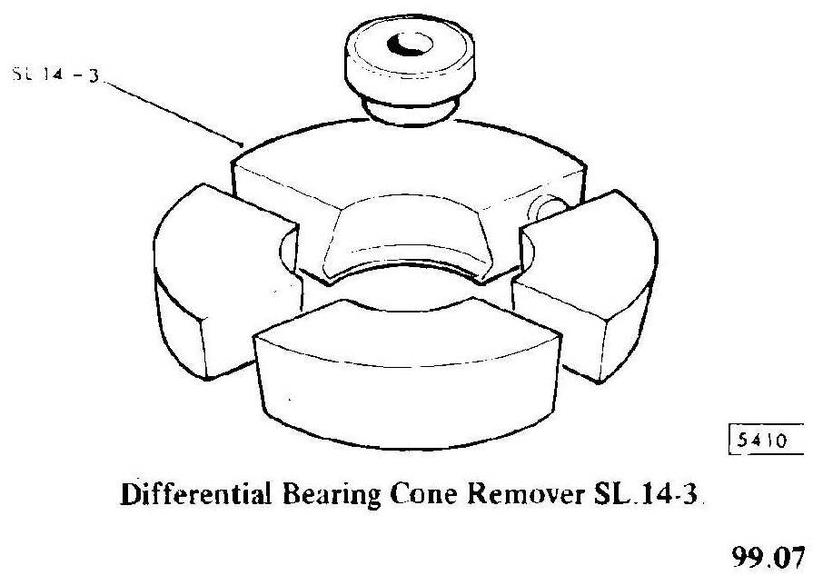
If I had one I might be able to see how it works.
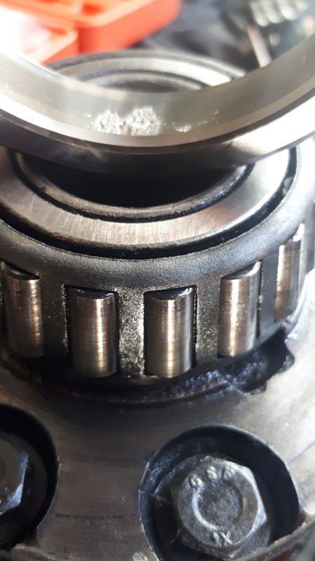
The diameter of the base of the bearing cone (inner race) is 64 mm. Per previous photo, the bearing sits on a machined shoulder, diameter of this shoulder is slightly more than 64 mm, i.e. the base of the bearing does not overhang, there is no protruding part of the cone/inner race for a clamshell lip to fit under.
The shims are between the cone and the shoulder. Shim OD is 57 mm therefore there is a 3.5 mm deep groove between the bearing and its seat that is the width of the shims, in my case 0.99 mm on one side, 0.93 mm on the other, I’m discounting this as too narrow and unreliable for anchoring a clamshell puller.
The only explanation I can think of is that jaguar service tool is designed to hook under the roller cage however that would be wrong in so many ways … So, I am a bit stumped.
I was not expecting these differential bearings to be difficult to remove, as you note the alignment process is for them to be installed and reinstalled. I have tried levering, to no avail. Now I’ve ordered that 2-jaw puller, if that doesn’t work I’ll try wedging them off by working around the shim grooves with a cold chisel, if that doesn’t work then yes, I’ll maybe have to resort to the grinder...
If I had one I might be able to see how it works.
The diameter of the base of the bearing cone (inner race) is 64 mm. Per previous photo, the bearing sits on a machined shoulder, diameter of this shoulder is slightly more than 64 mm, i.e. the base of the bearing does not overhang, there is no protruding part of the cone/inner race for a clamshell lip to fit under.
The shims are between the cone and the shoulder. Shim OD is 57 mm therefore there is a 3.5 mm deep groove between the bearing and its seat that is the width of the shims, in my case 0.99 mm on one side, 0.93 mm on the other, I’m discounting this as too narrow and unreliable for anchoring a clamshell puller.
The only explanation I can think of is that jaguar service tool is designed to hook under the roller cage however that would be wrong in so many ways … So, I am a bit stumped.
I was not expecting these differential bearings to be difficult to remove, as you note the alignment process is for them to be installed and reinstalled. I have tried levering, to no avail. Now I’ve ordered that 2-jaw puller, if that doesn’t work I’ll try wedging them off by working around the shim grooves with a cold chisel, if that doesn’t work then yes, I’ll maybe have to resort to the grinder...
Regards,
ColinL
'72 OTS manual V12
ColinL
'72 OTS manual V12
| Link: | |
| BBcode: | |
| HTML: | |
| Hide post links |
-
lowact
Topic author - Posts: 760
- Joined: Mon Oct 09, 2017 10:05 am
- Location: Canberra, Australia
- Contact:
#8 Re: Differential case side bearings
Hello Bill, why am I not surprised? Very keen to know how a a clamshell puller works in this case, maybe next time the lock-downs coincide I can swing by for an explanation?
My plan for aligning the new CWP is to measure the new bits and the old bits incl. brgs and add/subtract shims as required to cancel any difference, assemble and check the contact pattern, adjust and repeat ...
Regards,
ColinL
'72 OTS manual V12
ColinL
'72 OTS manual V12
| Link: | |
| BBcode: | |
| HTML: | |
| Hide post links |
#9 Re: Differential case side bearings
Hello Colin,
You're using shims to set the pre-load of the Pinion Bearings, but anyone refurbishing a differential from an S3 E Type and following the S3 Workshop manual, disregard completely the way in which setting the pre-load of the pinion bearings is described; it is simply wrong.
Its stated that the Companion Flange nut is tightened to 120lb/ft to 140lb/ft and that's it, finished and if you inadvertently exceed 140lb/ft torque, you have to discard the collapsible spacer and start again; all hogwash. To do as instructed will result in a shite load of end play.
The position of the Pinion Gear relative to the centre of the Crown-wheel is set before setting the backlash between the Pinion and Crown-wheel. Once that's done, but with the Crown-wheel assembly removed, torque the Companion Flange nut up to between 130lb/ft to 140lb/ft, on a stack of shims that will result in measurable end play. Measure the end play using a dial indicator, then remove shims equal to the end play, plus 0.001" (0.025mm). Reassemble and torque the Companion Flange Nut to between 130lb/ft to 140lb/ft then, using a lb/in torque wrench, measure the amount of torque required to start and keep rotating the Pinion Shaft; the target is 26lb/in torque, which is adjusted by adding or subtracting shims. Use a new Cone-Loc nut in the final assembly.
The torque specified to turn the Pinion Shaft when setting the Pre-load of an S1 differential was 8lb/in to 12lb/in. 26lb/in comes from that specified for XJS and other V12 cars that use a collapsible spacer. The pre-load should be the same whether shims or a collapsible spacer is used. Accordingly, if a collapsible spacer system is used, the Companion Flange Nut is tightened until 26lb/in torque is required to rotate the Pinion Shaft without any reference to the torque applied to the Companion Flange Nut when tightening it. You will find that the torque on Companion flange Nut will be well in excess of 140lb/ft torque by the time 26lb/in torque to rotate the Pinion Shaft is reached; usually up around 200lb/ft torque, which is still well below the yield point of a screw thread the size of the Pinion Shaft.
Best regards,
Bill
| Link: | |
| BBcode: | |
| HTML: | |
| Hide post links |
#10 Re: Differential case side bearings
Hi Bill...what modification have you made to a clam shell puller.......the central cone part of the bearing sits well down on the shims with little or no lip to get the clam under.....typically the clam puller is just used and ends up pulling the bearing off by the cage part with the rollers..it will damage the bearing but they would be replaced anyway......as mentioned you then have to set it up with the correct shim pack...which means again pressing and pulling bearings....so dummy/reamed out bearing are used so theycan be slips on/ off easy to set shim requirements without the need for a puller......Steve
Steve
69 S2 2+2 (sold) ..Realm C type replica, 1960 xk150fhc
69 S2 2+2 (sold) ..Realm C type replica, 1960 xk150fhc
| Link: | |
| BBcode: | |
| HTML: | |
| Hide post links |
#11 Re: Differential case side bearings
Steve Wrote:
Its a puller I made based on the same principle as a clam shell puller, but made using A2 Tool Steel and heat treated after machining. It has a sharp tapered leading edge that can make a start between the shims and the bearing to start to move the bear. The A2 Tool Steel has proved tough enough to resist failure of the fine tapered edge.
Using a dummy bearing as you've described would get you close, but I wouldn't consider that method for a moment in the final analysis; there are stacked tolerances that makes that system not totally reliable. Particularly with the puller I have, I have no problems removing bearing with zero fear of damage.
Regards,
Bill
Hello Steve,what modification have you made to a clam shell puller.......the central cone part of the bearing sits well dowm on the shims with little or no lip to get the clam under.....typically the clam puller is just used and ends up pulling the besting off by the cage part with the rollers..it will damage the bearing but they would be replaced anyway......as mentioned you then have to set it up with the correct shim pack...which means again pressing and pulling bearings....so dummy/reamed out bearing are used so theycan be slips on/ off easy to set shim requirements without the need for a puller
Its a puller I made based on the same principle as a clam shell puller, but made using A2 Tool Steel and heat treated after machining. It has a sharp tapered leading edge that can make a start between the shims and the bearing to start to move the bear. The A2 Tool Steel has proved tough enough to resist failure of the fine tapered edge.
Using a dummy bearing as you've described would get you close, but I wouldn't consider that method for a moment in the final analysis; there are stacked tolerances that makes that system not totally reliable. Particularly with the puller I have, I have no problems removing bearing with zero fear of damage.
Regards,
Bill
| Link: | |
| BBcode: | |
| HTML: | |
| Hide post links |
#12 Re: Differential case side bearings
Hi Bill...obviously not up to you standards but Colin needs a way to diy this job......... thought it was standard practice in many shops to use dummy bearing set to set up shims........sets widely available.....Steve
Steve
69 S2 2+2 (sold) ..Realm C type replica, 1960 xk150fhc
69 S2 2+2 (sold) ..Realm C type replica, 1960 xk150fhc
| Link: | |
| BBcode: | |
| HTML: | |
| Hide post links |
#13 Re: Differential case side bearings
Steve Wrote:
I've observed sufficient variations in like brand taper roller bearings to not use the method of a dummy bearing and I don't see it being a standard practice among drive line repairers here. However, I'd be happy to do so, if first the height of the actual replacement bearing cones were compared with the dummy bearings. I would do this by placing the bearings to be compared on a surface plate and compare the height with a dial indicator on a height gauge in conjunction with a common bearing cup place on each bearing cone and a load applied. Note any variation and use it when calculating the number and distribution of shims to achieve the correct backlash.
With regards to Colin using this method, it would be important that the dummy bearings be very accurately prepared to achieve an accurate result and because the bearing to be used as the dummy can't be held on the outside when machining the bore to be a running fit on the diff journals, its not such an easy part to set up. By the time all this gear is prepared for a potentially one off use, it would be easier to prepare a workable bearing puller.
Regards,
Bill
Hello Steve,thought it was standard practice in many shops to use dummy bearing set to set up shims........sets widely available.
I've observed sufficient variations in like brand taper roller bearings to not use the method of a dummy bearing and I don't see it being a standard practice among drive line repairers here. However, I'd be happy to do so, if first the height of the actual replacement bearing cones were compared with the dummy bearings. I would do this by placing the bearings to be compared on a surface plate and compare the height with a dial indicator on a height gauge in conjunction with a common bearing cup place on each bearing cone and a load applied. Note any variation and use it when calculating the number and distribution of shims to achieve the correct backlash.
With regards to Colin using this method, it would be important that the dummy bearings be very accurately prepared to achieve an accurate result and because the bearing to be used as the dummy can't be held on the outside when machining the bore to be a running fit on the diff journals, its not such an easy part to set up. By the time all this gear is prepared for a potentially one off use, it would be easier to prepare a workable bearing puller.
Regards,
Bill
| Link: | |
| BBcode: | |
| HTML: | |
| Hide post links |
-
lowact
Topic author - Posts: 760
- Joined: Mon Oct 09, 2017 10:05 am
- Location: Canberra, Australia
- Contact:
#14 Re: Differential case side bearings
An update, after Round 1, Jaguar has all the points, the humptydumptyengineeringcumpny still languishing on zero. Ultimately I will win, because I have an angle grinder and enough cutting discs to see out a pandemic.
I first tried to give my diff refurb/upgade job to the local diff guru. He reckoned he didn’t need to know the Jaguar settings/tolerances because the diff would tell him how much backlash it needed, his workmanship would be perfect, if there were any issues it would be the fault of the new Quaif CWP that I was providing, not down to him. It was after deciding to do it myself that I discovered I’d mistakenly purchased an S1 CWP. My middle name should be “Lucky”.
To fit new diff side bearings, the procedure requires you to prefit, measure and remove the bearings without shims. For this a clamshell puller, that only works if there is a shim gap, couldn’t work?
Dummy bearings, reamed out so as not to require much pulling, may work, considering that the ultimate test is visual inspection of the CWP contact pattern, compared to which bearing manufacturing tolerances would not be significant? But, what do after you’ve put it all together with the real bearings only to discover that it’s not quite perfect?
I was optimistic that my modified tool-steel (Cr-V) 2-jaw puller would work but, it broke. Round 2 tomorrow…
And Bill, thanks for the advice re pinion pre-loading. I’d already trawled the forum looking for everything you’d previously posted on this subject. I’ll be trying for the double, 26 lb.inch friction to be achieved by only 130ish lb.ft of tightening, by judicious trial and error selection of shims. Coming 2nd after the 1st round of that also, not enough shims …
Regards,
ColinL
'72 OTS manual V12
ColinL
'72 OTS manual V12
| Link: | |
| BBcode: | |
| HTML: | |
| Hide post links |
#15 Re: Differential case side bearings
Hi Colin your making it reallt difficult.......a clam shell puller will remove the bearing....you going to replace them anyway..they will get damaged as you pull them off....or cut the outer race and rollers off....set up your puller and heat the inner cone as you pull.........make up an easy slid on dummy bearing.....or purchase dummy bearings.....google them..they are expensive so a standard bearing held in a vice and reamed out with a flap sander on a drill.....also google to see side bearings removed with clam shell and dummy bearings made.....Steve
Steve
69 S2 2+2 (sold) ..Realm C type replica, 1960 xk150fhc
69 S2 2+2 (sold) ..Realm C type replica, 1960 xk150fhc
| Link: | |
| BBcode: | |
| HTML: | |
| Hide post links |
#16 Re: Differential case side bearings
Steve Wrote:
Timken Bearings are being made in China and my observation of their tolerance is that they are rubbish. For Taper Roller Bearings I'm now using Koyo bearings.
Those using dummy, easy to remove bearing, if the precaution is not made of measuring the height of the dummy bearing cone seated in the new cup that will be used in the differential and comparing it with the height of the actual bearing cone that will be used in the differential, measured the same way, then they are in the same category as the local diff guru Colin referred to, "that didn’t need to know the Jaguar settings/tolerances because the diff would tell him how much backlash it needed".
If you were to use Timken Taper Roller Bearing from China, and disregard any difference between the dummy and actual bearing set to be used in the differential, then the chances of having the tooth contact either too close to either the small or large end of the tooth form will be high.
Anyone that says they can disregard the backlash specified by the marking on the Crown-wheel is just making it harder for themselves and starting from a guess point.
Ultimately, when checking the tooth contact markings, the actual final fit bearing cones have to be used. If the marking is not optimal with regards to the small and large end of the tooth form, then you will be where Colin is at present; trying to remove the bearing without damaging them.
Regards,
Bill
Hello Steve,make up an easy slid on dummy bearing.....or purchase dummy bearings.....google them..they are expensive so a standard bearing held in a vice and reamed out with a flap sander on a drill.
Timken Bearings are being made in China and my observation of their tolerance is that they are rubbish. For Taper Roller Bearings I'm now using Koyo bearings.
Those using dummy, easy to remove bearing, if the precaution is not made of measuring the height of the dummy bearing cone seated in the new cup that will be used in the differential and comparing it with the height of the actual bearing cone that will be used in the differential, measured the same way, then they are in the same category as the local diff guru Colin referred to, "that didn’t need to know the Jaguar settings/tolerances because the diff would tell him how much backlash it needed".
If you were to use Timken Taper Roller Bearing from China, and disregard any difference between the dummy and actual bearing set to be used in the differential, then the chances of having the tooth contact either too close to either the small or large end of the tooth form will be high.
Anyone that says they can disregard the backlash specified by the marking on the Crown-wheel is just making it harder for themselves and starting from a guess point.
Ultimately, when checking the tooth contact markings, the actual final fit bearing cones have to be used. If the marking is not optimal with regards to the small and large end of the tooth form, then you will be where Colin is at present; trying to remove the bearing without damaging them.
Regards,
Bill
Last edited by angelw on Fri Aug 13, 2021 8:46 am, edited 1 time in total.
| Link: | |
| BBcode: | |
| HTML: | |
| Hide post links |
#17 Re: Differential case side bearings
Hi Bill.....i currently have 3 sets of Timken bearings...purchased new from SNGB.....all have Timken USA on them and the boxes also have "printed" in USA...........Im assumeing they arnt made in China...i could be wrong......If useing dummy bearings to set up the shimming it should be very obvious that you would need to as accuratly as possible measuer the dummy and the new bearings to be used and adjust shimmind as required........Steve
Steve
69 S2 2+2 (sold) ..Realm C type replica, 1960 xk150fhc
69 S2 2+2 (sold) ..Realm C type replica, 1960 xk150fhc
| Link: | |
| BBcode: | |
| HTML: | |
| Hide post links |
-
lowact
Topic author - Posts: 760
- Joined: Mon Oct 09, 2017 10:05 am
- Location: Canberra, Australia
- Contact:
#18 Re: Differential case side bearings
I like to think the opposite, just trying the simplest cheapest (AUD80) non-destructive method first, before resorting to a destructive method. In this case it worked; Round 2 was a success (yay).
Just as well because, I expect I will need to be able to remove/reinstall the new bearings to move shims around a few times until I get it sufficiently perfect…
Strange that Jaguar never updated their tool list. The diff has recesses for a two leg puller. Instead SL.14-3 is a sort of clamshell puller that cannot fit or function as per the manual, if used it is destructive.
I belatedly googled “diff side bearing puller” and discovered that they are a thing, two-leg with a cross-bolt that would make my G-clamp superfluous, but all with hooks too big and not tool-steel, so would not be strong enough when trimmed to fit. The puller I used came with 3 sets of legs each with removable tool-steel hooks so I had spares. For the “Round 2” I trimmed a 2nd set not quite as much. And took extra car to ensure it was centered and pulling evenly.
Regarding backlash, the workshop manual says two things:
- Don’t set the backlash less than 0.1 mm otherwise the diff will be noisy.
The backlash setting should be engraved on the ring-gear.
My understanding is that, when setting up a new crown-wheel, the ideal backlash would be as above, close to but not less than 0.1 mm?
Regards,
ColinL
'72 OTS manual V12
ColinL
'72 OTS manual V12
| Link: | |
| BBcode: | |
| HTML: | |
| Hide post links |
#19 Re: Differential case side bearings
Colin Wrote:
Crown-wheel and Pinions should be supplied as sets and are lapped together as part of the manufacturing process. When lapping, the Crown-wheel and Pinion are set so that the primary contact is evenly spaced between the small and large end of the Crown-wheel tooth and the backlash value should be engraved on the Crown-wheel at that time. Accordingly, the value engraved on the Crown-wheel will be very close to what the backlash needs to be.
When setting up a new Crown-wheel/Pinion Set in the diff, the ideal back lash is that which results in the witness mark being evenly spaced between the small and large end of the tooth.
Best regards,
Bill
Hello Colin,My understanding is that the engraving on the ring gear was by the installer. I.e. this number is not what the backlash needs to be, it is just what it is (or was). It is not a design requirement, it is an installation record. New crown wheels, that have never been installed, will not have a backlash number engraved on them.
My understanding is that, when setting up a new crown-wheel, the ideal backlash would be as above, close to but not less than 0.1 mm?
Crown-wheel and Pinions should be supplied as sets and are lapped together as part of the manufacturing process. When lapping, the Crown-wheel and Pinion are set so that the primary contact is evenly spaced between the small and large end of the Crown-wheel tooth and the backlash value should be engraved on the Crown-wheel at that time. Accordingly, the value engraved on the Crown-wheel will be very close to what the backlash needs to be.
When setting up a new Crown-wheel/Pinion Set in the diff, the ideal back lash is that which results in the witness mark being evenly spaced between the small and large end of the tooth.
Best regards,
Bill
| Link: | |
| BBcode: | |
| HTML: | |
| Hide post links |
-
lowact
Topic author - Posts: 760
- Joined: Mon Oct 09, 2017 10:05 am
- Location: Canberra, Australia
- Contact:
#20 Re: Differential case side bearings
My Quaife CWP has the pinion mounting distance, which is the req'd setting of the pinion relative to the crown wheel, and the cwp matching set no., on the pinion and just the cwp set number on the crown wheel, there is no backlash value. Imo if there was, it would be over spec'd.
Regards,
ColinL
'72 OTS manual V12
ColinL
'72 OTS manual V12
| Link: | |
| BBcode: | |
| HTML: | |
| Hide post links |