


Hi Rob Gill here,
Have fitted a O/D gearbox .
What is the best ,safest way to wire it up perminantly?.
Thanks
wiring diagram for overdrive unit
-
Jack the lad
- Posts: 106
- Joined: Mon Aug 18, 2014 5:44 pm
- Location: Newton Abbot, Devon

#2 Re: wiring diagram for overdrive unit
Please supply the details of which make and model of o/d that you have fitted. The most common make is the Laycock in a couple of types and I do have wiring diagrams for them. A precautionary note, none of the Laycock units will transmit the torque available from the V12 unit and would be liable to self-destruct.
| Link: | |
| BBcode: | |
| HTML: | |
| Hide post links |

#3 Re: wiring diagram for overdrive unit
Hi Colin....lots of info on the forum re overdrive in a S3....a quick search found this...with diagrams etc...Steve viewtopic.php?f=6&t=12072
Steve
69 S2 2+2 (just sold) ..Realm C type replica, 1960 xk150fhc
69 S2 2+2 (just sold) ..Realm C type replica, 1960 xk150fhc
| Link: | |
| BBcode: | |
| HTML: | |
| Hide post links |
-
dal2.0litrefrogeye
- Posts: 1074
- Joined: Fri Aug 06, 2010 10:48 pm
- Location: sarf london
- Contact:
#4 Re: wiring diagram for overdrive unit
If you don't have one by tomorrow , pm me and I can draw you the diagram ,
It's very simple , but does need a relay to protect the switch ,
Also try and get a nos solenoid. The new ones are chocolate teapot territory , I had 2 new ones let me down on a build in under 200 miles . Until I got a nos Lucas from Dave at Od spares
It's very simple , but does need a relay to protect the switch ,
Also try and get a nos solenoid. The new ones are chocolate teapot territory , I had 2 new ones let me down on a build in under 200 miles . Until I got a nos Lucas from Dave at Od spares
Its a way of life not a hobby
Darren . 64 4.2 modded 69 4.2
Darren . 64 4.2 modded 69 4.2
| Link: | |
| BBcode: | |
| HTML: | |
| Hide post links |


#5 Re: wiring diagram for overdrive unit
The OD “inhibit”switch only allows OD when in 4th gear (so that OD will not be torque overloaded). For s3 e-types the oem arrangement (no OD) has the gearbox breather pipe connecting to where the OD inhibit switch needs to go, this is so that the breather elbow and hose are forwards and low enough to fit, with clearance for movement, under the very low profile gearbox tunnel cover (BD36658). Sidenote: SNGB catalog shows the gearbox breather connecting to the 3rd (centre) port on the topcover, same as the xj6’s. This is incorrect for etypes, the breather cannot connect here without fouling the tunnel cover.
When a 4th gear (OD inhibit) switch is installed the gearbox breather is nevertheless moved to the centre port, the tunnel cover then needs to be panel-beaten to get the required clearance above the breather and also above the inhibit switch, allowing for movement as the gearbox floats on its mounting spring.
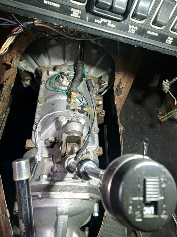
Here is pic of my S3 gearbox top cover showing the OD “select” switch on the gearlever knob (aka xj6) the OD “inhibit” switch on the top cover (front-left), and the gearbox breather relocated to the centre port:
And here is pic of my tunnel cover during panel-beating …
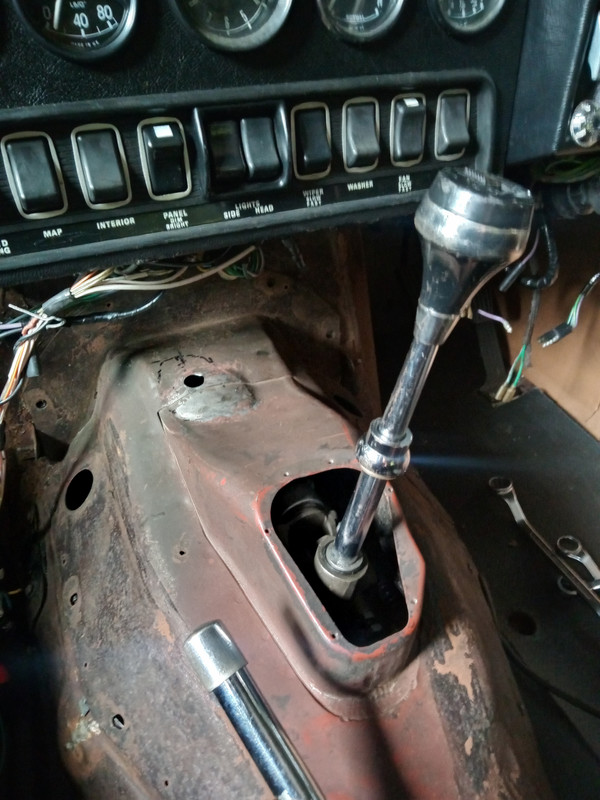
Note that there may appear to be adequate clearance without panel-beating if the gearbox mounting spring has not been upgraded (C12299 > C19988). With OD fitted the gearbox is heavier, the oem manual gearbox mounting spring (C12299) is fully compressed, the gearbox sits low. Solution is to replace this spring and associated bits with the auto transmission version (C19988). Gearbox with OD is then supported properly, floating level on damped spring support.
Imo the Jaguar (oem xj6) arrangement without OD relay, per post 21 in Steve’s linked discussion, is best design, depending on your switch. The Jaguar design uses an 8 amp fuse with the wiring (incl. switches) rated well above this. When the OD is engaged it momentarily draws ~15 amp, for too short a time to blow the 8 amp fuse. If there is a fault and the current persists, the fuse will quickly blow to reliably protect the higher rated wiring and switches. In comparison a relay would be "treating the symptom not the cause" an unnecessary extra that's just one more thing that can go wrong?
If you are not opting for a switch on the gearlever knob there are plenty of adequately rated switches to choose from. If like me you want a switch on the gearlever knob there are 3 issues:
Issue #1 is the fact that a gearlever knob/switch has to be removed and unwired just to remove your console, design needs to enable this easily …
Issue #2 is the small size (diameter) of the centre bored hole for the wiring to pass up the (xj6) gear stick; for installation and removal you want the wiring to easily slide up and down. Solution is to use Tefzel wiring. AWG14 sized Tefzel wiring is rated for continuous 16A and is small and stiff enough for the two wires together to be to be easily pushed up and pulled down in the gear lever as required.
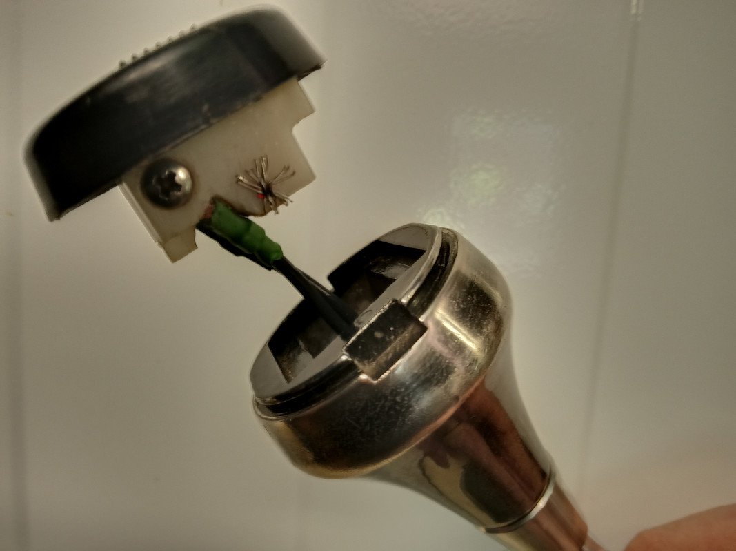
Issue #3 is the Leyland/Lucas (MG, Triumph, Jaguar) gearlever knob/switch. It is difficult to overstate how bad this thing is. One solution is to design/make your own, there’s been a few inspirational examples posted eleswhere, e.g. Marek’s, Ole’s …
I opted to use the “original” knob/switch after making some mods. The oem design has “C” shaped connectors on the wires that slide onto the edges of the switch terminals. Perhaps originally these connectors had sufficient tensile strength to reliably grip the terminals, today’s offerings do not. My solution was to crimp eyelets onto the wires and to modify the switch so that these are screw connected. I also cut away some of the switch so that the relatively stiff Tefzel wiring could be relatively straight, makes removal/reinstallation relatively easy ... did mean I had to drill and install an insulated pin (bit of Tefzel) to hold the switch together …
For me the simplest wiring is to take power from the reverse switch green wire. Feed it through the selector switch and the inhibit switch in series. Then feed it into the cockpit through the reverse switch wire grommet, to an accessible in-line 8A fuse (behind the guages). Then two wires from the fuse, one to an OD indicator lamp, the other back through the grommet to the OD solenoid.
When a 4th gear (OD inhibit) switch is installed the gearbox breather is nevertheless moved to the centre port, the tunnel cover then needs to be panel-beaten to get the required clearance above the breather and also above the inhibit switch, allowing for movement as the gearbox floats on its mounting spring.
Here is pic of my S3 gearbox top cover showing the OD “select” switch on the gearlever knob (aka xj6) the OD “inhibit” switch on the top cover (front-left), and the gearbox breather relocated to the centre port:
And here is pic of my tunnel cover during panel-beating …
Note that there may appear to be adequate clearance without panel-beating if the gearbox mounting spring has not been upgraded (C12299 > C19988). With OD fitted the gearbox is heavier, the oem manual gearbox mounting spring (C12299) is fully compressed, the gearbox sits low. Solution is to replace this spring and associated bits with the auto transmission version (C19988). Gearbox with OD is then supported properly, floating level on damped spring support.
Imo the Jaguar (oem xj6) arrangement without OD relay, per post 21 in Steve’s linked discussion, is best design, depending on your switch. The Jaguar design uses an 8 amp fuse with the wiring (incl. switches) rated well above this. When the OD is engaged it momentarily draws ~15 amp, for too short a time to blow the 8 amp fuse. If there is a fault and the current persists, the fuse will quickly blow to reliably protect the higher rated wiring and switches. In comparison a relay would be "treating the symptom not the cause" an unnecessary extra that's just one more thing that can go wrong?
If you are not opting for a switch on the gearlever knob there are plenty of adequately rated switches to choose from. If like me you want a switch on the gearlever knob there are 3 issues:
Issue #1 is the fact that a gearlever knob/switch has to be removed and unwired just to remove your console, design needs to enable this easily …
Issue #2 is the small size (diameter) of the centre bored hole for the wiring to pass up the (xj6) gear stick; for installation and removal you want the wiring to easily slide up and down. Solution is to use Tefzel wiring. AWG14 sized Tefzel wiring is rated for continuous 16A and is small and stiff enough for the two wires together to be to be easily pushed up and pulled down in the gear lever as required.
Issue #3 is the Leyland/Lucas (MG, Triumph, Jaguar) gearlever knob/switch. It is difficult to overstate how bad this thing is. One solution is to design/make your own, there’s been a few inspirational examples posted eleswhere, e.g. Marek’s, Ole’s …
I opted to use the “original” knob/switch after making some mods. The oem design has “C” shaped connectors on the wires that slide onto the edges of the switch terminals. Perhaps originally these connectors had sufficient tensile strength to reliably grip the terminals, today’s offerings do not. My solution was to crimp eyelets onto the wires and to modify the switch so that these are screw connected. I also cut away some of the switch so that the relatively stiff Tefzel wiring could be relatively straight, makes removal/reinstallation relatively easy ... did mean I had to drill and install an insulated pin (bit of Tefzel) to hold the switch together …
For me the simplest wiring is to take power from the reverse switch green wire. Feed it through the selector switch and the inhibit switch in series. Then feed it into the cockpit through the reverse switch wire grommet, to an accessible in-line 8A fuse (behind the guages). Then two wires from the fuse, one to an OD indicator lamp, the other back through the grommet to the OD solenoid.
Regards,
ColinL
'72 OTS manual V12
ColinL
'72 OTS manual V12
| Link: | |
| BBcode: | |
| HTML: | |
| Hide post links |
#6 Re: wiring diagram for overdrive unit
Dear Rob,
you want to wire it up as follows:-
1/ it must not operate in reverse gear
2/ it is operated via a relay, so the overdrive switch is used for the relay winding, not the overdrive directly
3/ at your option, you an make it not operate in any gear other than 4th.
1/ There is a reverse gear switch on top of the gearbox which is supplied by a green wire and then sends light to the reverse lights via a green/brown wire if reverse gear is selected. If you want you can run the green/brown wire to a Lucas changeover relay W1 winding and earth the W2 winding. This can be used to power a relay to lockout the overdrive if reverse is selected.
2/ The overdrive solenoid pulls about 15-19amps when it first operates and then uses about 1amp to stay open. This means you cannot safely run the overdrive solenoid directly through a switch - it must be run by a heavy duty relay. If wiring a Lucas relay as above, take a brown wire to the C2 contact and take C3 to the overdrive solenoid.
3/ There is a second switch location on the top cover of a standard Jaguar gearbox over the 4th gear position. If you run you green relay winding supply through this, the overdrive relay winding can only operate the relay in 4th gear.
You need an overdrive switch to be in the relay winding 12v supply side. Whether that comes through just a 4th gear switch, or whether that comes before a Lucas relay W1 contact, is your choice. The former gives you the choice of having overdrive in any gear and the latter only if in 4th.
The gearbox ratios of a standard box and the overdrive percentage drop mean that there is almost no advantage or difference for 2nd or 3rd gears (2nd plus O/D is very close to 3rd; 3rd plus O/D is very close to 4th) but you do get a gear "1.5" between 1st and 2nd if you want it.
Contrary to above posts, the overdrive unit has no problem with being engaged in lower gears. I am not aggressive with the right foot and my O/D box has not disintegrated. I also never bothered with any panel beating, but I did bend the Lucar connectors on the switch down a little so the switch wiring wouldn't point directly upwards.
Basically, use a relay to power the overdrive solenoid and it's your choice as to whether that relay W1 winding only sees power if 4th is engaged via a switch OR use a switch to power a relay to keep your O/D locked out if in reverse.
Sketch those two options out on paper and you have your wiring diagram. One of them uses a 4th gear switch as a "not-lockout" before using a switch to power a relay winding; the other uses a changeover relay
to either power the reverse lights OR the overdrive relay mutually exclusively.
kind regards
Marek
| Link: | |
| BBcode: | |
| HTML: | |
| Hide post links |