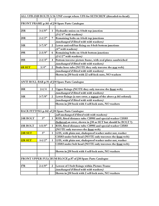
#1 Front Frame (or Picture Frame) Fasteners (again)
Posted: Sun Nov 19, 2023 3:44 pm
I was re-assembling my Series 1 front frames recently, and made some notes relating to the Front Frame, or Picture Frame, that would have helped me had I been able to refresh my memory with them before I started work, despite having done this before.
Assembling these to the shell for the first time is a daunting and complicated operation, because there is a multiplicity of other components that are fitted and/or sandwiched at the same time.
It's vital to work out beforehand what fasteners are used, and in what order and orientation parts are assembled, as you will have to fight to get some of the bolts into place.
A couple of foot-long 5/16" pry-bars with tapered/conical ends are essential - 8mm can be used too, provided you dress the first few inches down to 5/16" with a flap-disc on the lathe.
There is in fact a very detailed account, much referred to by others, of front-frame bolts by one Steve Kemp in the Knowledge Base of the UK E-Type Forum.
I did not find this particularly helpful in practice, for the picture-frame itself, unless you are trying to build a 100-point bolt-manufacturer-certified car, as it contains errors (bolts H ? hex cap screws ?) and I found its principal diagram (page 6) and its references hard to follow.
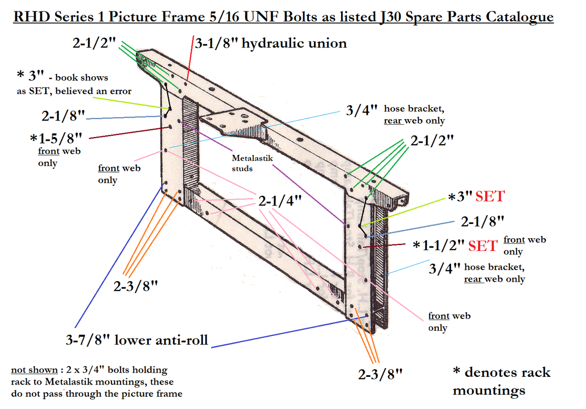
Hence my own annotated diagrams based around the J30 images.
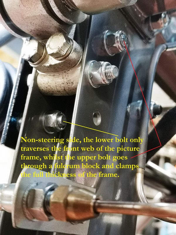
These ONLY relate to the actual picture frame fasteners - to qualify, the bolts have to go through the picture frame in some way.
The J30 parts book is very specific about the type and quantity of fasteners used across this complete assembly, but it requires some detective work to understand the nuances.
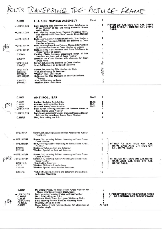
These are the relevant extracts.
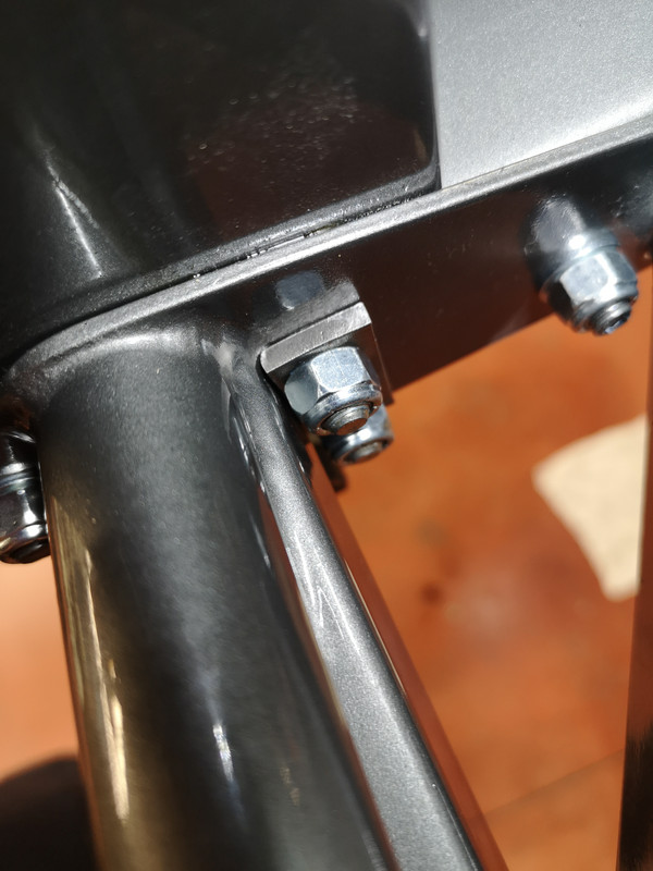
The first thing to note is that Jaguar never specified ANY washers on ANY of the principal fasteners (with a couple of specific exceptions including the steering rack) over the complete front-frame structure.
The other exceptions are the 12 plain washers specified as being "under Nuts C8667/2" for the 24 bolts listed as "securing Side Members to dash".
This can only mean they were used on the 12 locations where there are no pre-threaded inserts in the shell, and so under the nuts of the 12 x 3/4" bolts concerned, presumably to improve the stress distribution.
What this means is that all the other fasteners, bolt heads and nuts, were tightened up directly against the paint.
There is ample confirmation of this somewhat surprising approach on the many Factory Fit photographs visible on the UK E-Type Forum, but with modern paints generally being applied more thickly than in the 1960's it requires a brave mechanic to follow that same approach today.
Note the rippled paint around assembly surfaces, and this had been dry/hard for 6 months when bolted up.
If you decide to use washers, then, you need to factor this in when you come to decide on the bolt-lengths you are going to use - a pair of zinc Namrick 5/16" steel washers is going to add 1/16" under both bolt and nut heads, or 1/8" to the thickness you are clamping, and in some cases this will mean that the Nyloc nuts are not sufficiently traversed by the bolt.
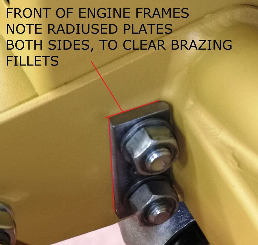
You may find, like I did, that there may be a fillet of braze, in some locations, that stops you using washers - in which case a radiused pad like this can help.
The table I have written shows both the original specified lengths for an assembly using no washers, and which bolts I found that needed to be longer than original when using washers at both ends, which - for reasons both of paint-protection and stress-distribution - is what I have done on my own car.
You could argue that every bolt needs to be 1/8" longer, but in practice I have found that this is not the case ; in aircraft and racing applications it is generally accepted that there should be 2 full threads beyond the nylon, but in 20 years with my own car I have never had any of these bolts come loose even when there was just 1 thread, or even with the end flush.
It's for you to choose.
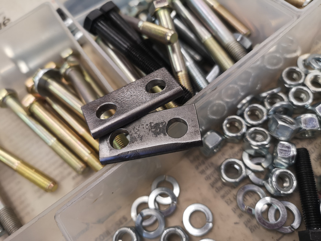
I would suggest you avoid the "bolt kits" retailed by one (rather loud) place in the States, as - despite the hyperbole - I found the one I bought in 2021 to be distinctly underwhelming, containing none of the many 1/8" and 1/4" nuances present in the 2 to 3 inch range, and it included 50-odd flat washers of 3/4" OD (Seen below, Right) when - if you're going to use washers - 5/8" (Seen below, Left) is what the Factory used and is far more elegant. Their components are great quality, but many are simply the wrong size.
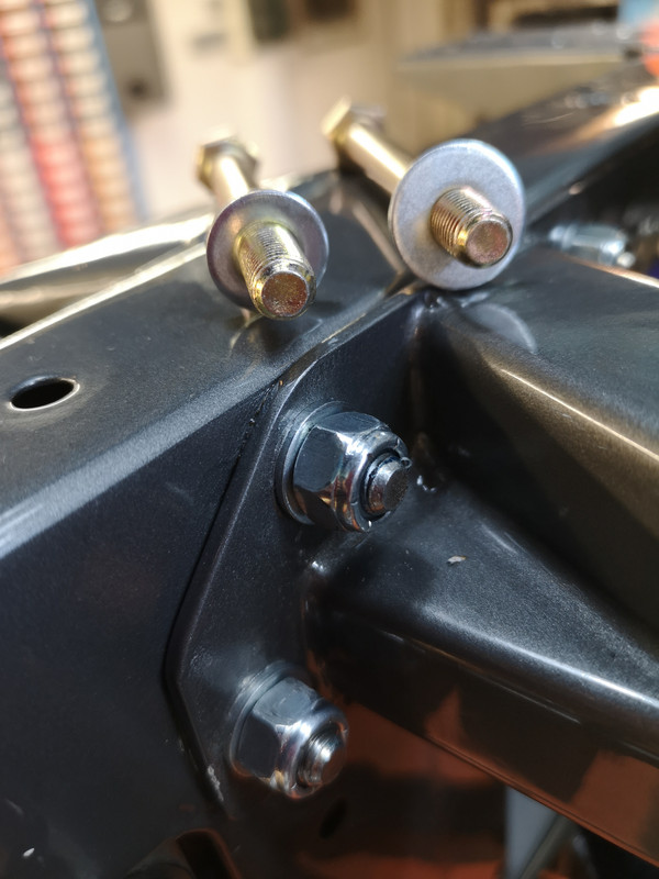
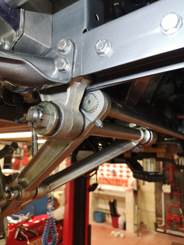
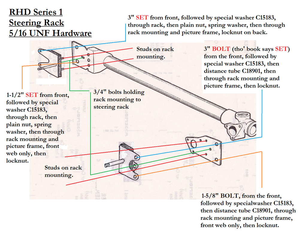
This next diagram attempts to show exactly how the steering rack was fitted.
The nuances of the Fail-Safe bolt/washer/spacer fastening were discussed here
viewtopic.php?f=4&t=5101&p=165137&hilit=fail#p165137
but in order to make this post more complete, for reference purposes, I've added the relevant section as follows :
This is what I think I've understood, with some pictures that I am pretty confident are the translation of the Parts Catalogue J30 components into their actual context.
Because I Is Dumb[/b] - it's what I would have liked to have access to, in words of one syllable, when assembling my car.
The nuances regarding the provision for fail-safe mounting of the steering-rack are legion, and I suspect many cars are assembled incorrectly - for there is no drawing of this in any publication I have seen, and the references to it in the Workshop Manuals - even the original one - are very far from being clear, to me.
At least, they're clear when you understand how it works.
Essentially, Jaguar needed to make sure that if the rubber mountings failed then the driver did not lose the steering - the rack being essentially bonded to the car via the mounting blocks, and if the rubbers fail, the rack will cease to steer the wheels.
On the Series 1, Jaguar treated the issue slightly differently at each end.
I understand the provision changed on later cars.
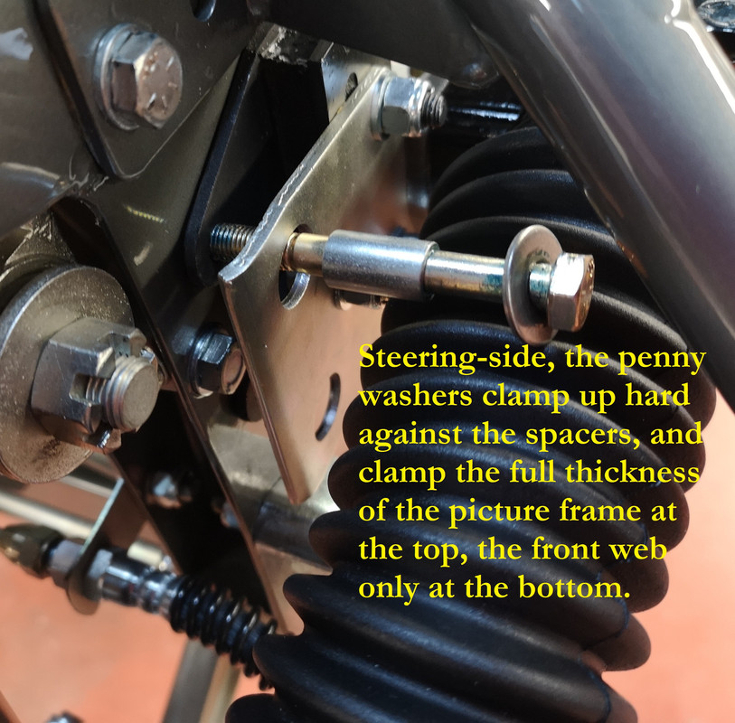
On the steering-wheel side they made a provision using spacers (referred to as "distance tubes" C18901 in J30) and "special" washers (C15183) so that in the case of a failed rubber the steering rack remained constrained both laterally and fore-and-aft ; the components are bolted up tight, with inbuilt gaps sufficient to keep the rack effectively rubber-mounted.
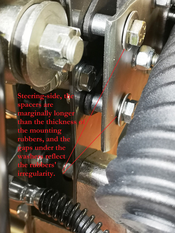
As supplied by SNGB, the Distance Tubes are 19.70mm long, 11.00mm OD, 8.50mm ID.
The Special Washer is 20.00mm OD and 1.50mm thick, basically any penny washer will do the business.
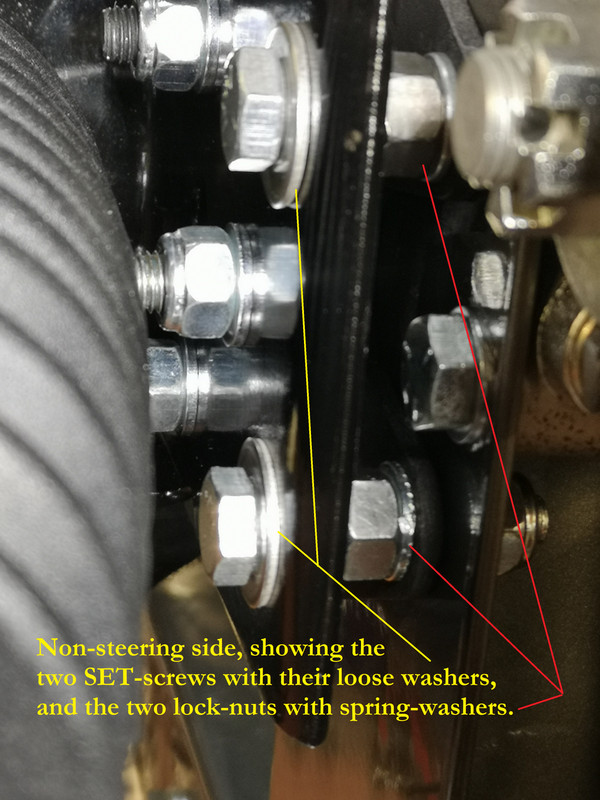
On the non-steering side, the same "special" washers are used, but - for reasons that nobody seems clear about - without the spacers ; the washers are then adjusted, in fact, to remain slightly loose, by the use of a locking plain-nut and spring-washer in the middle of the SET screws (threaded to head) that fasten the rack in place on that side.
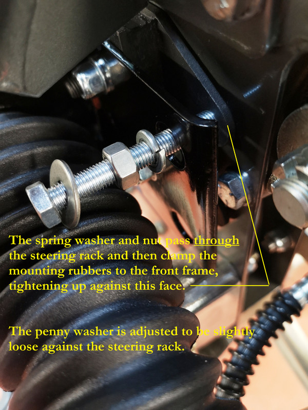
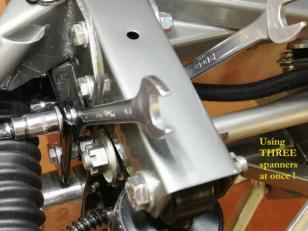
I found this surprisingly tricky to get right, as it really requires the use of three spanners on the same bolt.
This stops the rack falling away from the rubber should it fail, whilst not unduly interfering with the intended suppleness of the mounting.
Again somewhat unfathomably, Jaguar listed the same 3" SET screw for the upper fixation on both sides of these ensembles, when there is no sense or need for this on the steering-side, as a BOLT does the job just as well, or better.
Perhaps just for reasons of standardisation/rationalisation during assembly ?
It is very tempting to fit the spacers on all four mounting points, and thus duplicate the steering-wheel-side principle ; anyone who has done that might like to offer an opinion ?
And I'm equally open to any correction on any other parts of my "thesis".
Assembling these to the shell for the first time is a daunting and complicated operation, because there is a multiplicity of other components that are fitted and/or sandwiched at the same time.
It's vital to work out beforehand what fasteners are used, and in what order and orientation parts are assembled, as you will have to fight to get some of the bolts into place.
A couple of foot-long 5/16" pry-bars with tapered/conical ends are essential - 8mm can be used too, provided you dress the first few inches down to 5/16" with a flap-disc on the lathe.
There is in fact a very detailed account, much referred to by others, of front-frame bolts by one Steve Kemp in the Knowledge Base of the UK E-Type Forum.
I did not find this particularly helpful in practice, for the picture-frame itself, unless you are trying to build a 100-point bolt-manufacturer-certified car, as it contains errors (bolts H ? hex cap screws ?) and I found its principal diagram (page 6) and its references hard to follow.
Hence my own annotated diagrams based around the J30 images.
These ONLY relate to the actual picture frame fasteners - to qualify, the bolts have to go through the picture frame in some way.
The J30 parts book is very specific about the type and quantity of fasteners used across this complete assembly, but it requires some detective work to understand the nuances.
These are the relevant extracts.
The first thing to note is that Jaguar never specified ANY washers on ANY of the principal fasteners (with a couple of specific exceptions including the steering rack) over the complete front-frame structure.
The other exceptions are the 12 plain washers specified as being "under Nuts C8667/2" for the 24 bolts listed as "securing Side Members to dash".
This can only mean they were used on the 12 locations where there are no pre-threaded inserts in the shell, and so under the nuts of the 12 x 3/4" bolts concerned, presumably to improve the stress distribution.
What this means is that all the other fasteners, bolt heads and nuts, were tightened up directly against the paint.
There is ample confirmation of this somewhat surprising approach on the many Factory Fit photographs visible on the UK E-Type Forum, but with modern paints generally being applied more thickly than in the 1960's it requires a brave mechanic to follow that same approach today.
Note the rippled paint around assembly surfaces, and this had been dry/hard for 6 months when bolted up.
If you decide to use washers, then, you need to factor this in when you come to decide on the bolt-lengths you are going to use - a pair of zinc Namrick 5/16" steel washers is going to add 1/16" under both bolt and nut heads, or 1/8" to the thickness you are clamping, and in some cases this will mean that the Nyloc nuts are not sufficiently traversed by the bolt.
You may find, like I did, that there may be a fillet of braze, in some locations, that stops you using washers - in which case a radiused pad like this can help.
The table I have written shows both the original specified lengths for an assembly using no washers, and which bolts I found that needed to be longer than original when using washers at both ends, which - for reasons both of paint-protection and stress-distribution - is what I have done on my own car.
You could argue that every bolt needs to be 1/8" longer, but in practice I have found that this is not the case ; in aircraft and racing applications it is generally accepted that there should be 2 full threads beyond the nylon, but in 20 years with my own car I have never had any of these bolts come loose even when there was just 1 thread, or even with the end flush.
It's for you to choose.
I would suggest you avoid the "bolt kits" retailed by one (rather loud) place in the States, as - despite the hyperbole - I found the one I bought in 2021 to be distinctly underwhelming, containing none of the many 1/8" and 1/4" nuances present in the 2 to 3 inch range, and it included 50-odd flat washers of 3/4" OD (Seen below, Right) when - if you're going to use washers - 5/8" (Seen below, Left) is what the Factory used and is far more elegant. Their components are great quality, but many are simply the wrong size.
This next diagram attempts to show exactly how the steering rack was fitted.
The nuances of the Fail-Safe bolt/washer/spacer fastening were discussed here
viewtopic.php?f=4&t=5101&p=165137&hilit=fail#p165137
but in order to make this post more complete, for reference purposes, I've added the relevant section as follows :
This is what I think I've understood, with some pictures that I am pretty confident are the translation of the Parts Catalogue J30 components into their actual context.
Because I Is Dumb[/b] - it's what I would have liked to have access to, in words of one syllable, when assembling my car.
The nuances regarding the provision for fail-safe mounting of the steering-rack are legion, and I suspect many cars are assembled incorrectly - for there is no drawing of this in any publication I have seen, and the references to it in the Workshop Manuals - even the original one - are very far from being clear, to me.
At least, they're clear when you understand how it works.
Essentially, Jaguar needed to make sure that if the rubber mountings failed then the driver did not lose the steering - the rack being essentially bonded to the car via the mounting blocks, and if the rubbers fail, the rack will cease to steer the wheels.
On the Series 1, Jaguar treated the issue slightly differently at each end.
I understand the provision changed on later cars.
On the steering-wheel side they made a provision using spacers (referred to as "distance tubes" C18901 in J30) and "special" washers (C15183) so that in the case of a failed rubber the steering rack remained constrained both laterally and fore-and-aft ; the components are bolted up tight, with inbuilt gaps sufficient to keep the rack effectively rubber-mounted.
As supplied by SNGB, the Distance Tubes are 19.70mm long, 11.00mm OD, 8.50mm ID.
The Special Washer is 20.00mm OD and 1.50mm thick, basically any penny washer will do the business.
On the non-steering side, the same "special" washers are used, but - for reasons that nobody seems clear about - without the spacers ; the washers are then adjusted, in fact, to remain slightly loose, by the use of a locking plain-nut and spring-washer in the middle of the SET screws (threaded to head) that fasten the rack in place on that side.
I found this surprisingly tricky to get right, as it really requires the use of three spanners on the same bolt.
This stops the rack falling away from the rubber should it fail, whilst not unduly interfering with the intended suppleness of the mounting.
Again somewhat unfathomably, Jaguar listed the same 3" SET screw for the upper fixation on both sides of these ensembles, when there is no sense or need for this on the steering-side, as a BOLT does the job just as well, or better.
Perhaps just for reasons of standardisation/rationalisation during assembly ?
It is very tempting to fit the spacers on all four mounting points, and thus duplicate the steering-wheel-side principle ; anyone who has done that might like to offer an opinion ?
And I'm equally open to any correction on any other parts of my "thesis".