OK boys, you asked for it.
I have resuscitated all the old pictures, weeded out all the changed punctuation marks we got stuffed with when the Forum changed platforms, and generally wasted a couple of hours, so let's hope this is of some use to someone.
I must have been a lot brighter and sharper when I wrote this as reading it today (2017) freaks me out and would have me reaching for my cheque book and an alternator, however I obviously DID manage what I wrote and the car has worked perfectly ever since.
EDIT - re-establishing photo links and editing this in 2020 makes sobering reading - I was indeed a lot brighter in 2017 and in 2014 ! It's been downhill all the way, as I've since bought a Dynalite from Powerlite at DY5 3SU .......
Here goes :
Reading all the advice about adjusting the RB340, and other E-Type boxes, available in all sorts of different forms on the net, gave me a headache, and had me going around in circles. At one point, convinced I'd managed to bugger my genuine-original NOS one by my cack-handed adjustments, I was about to chuck it out and buy a solid-state one ....
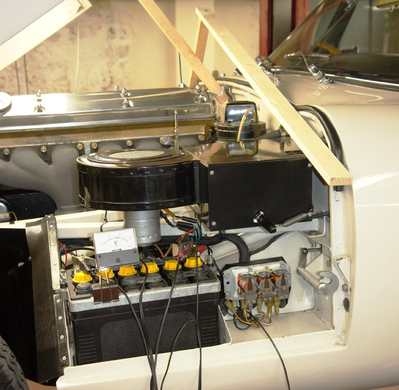
I offer here a synthesis of the reading I did and ended up applying with success, using the words of one syllable I would have liked to have stumbled across, written for a complete f----wit, in the hope that the many hours I wasted will be of some use to others.
Much of it is relevant to other control-boxes, not just the RB340.
I know from experience with engine-dynos that I tend to lose my wits and reason when confronted with revving engines and twitching dials, breathing carbon monoxide and waiting for rods to come through the side, so I made myself up a set of cards to slide under the control box during each of the 4 operations so that all was to hand and simplified, aimed at the intoxicated f----wit.
You will need the relevant reference pages relating to these control-boxes from the original Lucas Handbook, as of April 2020 this link still worked,
http://mgaguru.com/mgtech/books/pdf/Luc ... _Tests.pdf
It theoretically does contain all the necessary information, tho' I found misleading and indigestible - which is why I wrote this lot in fact.
Things to note :
A. With the original 3.8 harness, the regulator is fed from the battery with NO fused protection whatsoever - the brown/white wire feeding the B-B terminals is permanently live and mega-powerful ; if you were to manually close the Drop-Off contacts during any adjustments, they can weld shut and you can fritz the wiring harness back to the battery, and probably end up with a fire to extinguish.
I consider it absolutely imperative to fuse both the brown wires that leave the battery/starter-solenoid interface ( one goes to the ammeter, the other to fuses 3 and 8 ) before you do anything to the wiring on a 3.8.
See for details :
viewtopic.php?t=5214&highlight=
B. The revs expressed in many publications relate to Dynamo revs, NOT engine revs, so you need to be wary of what you read - and be kinder to your engine, because 3.000 dynamo rpm, for example, is actually only 1.800 engine rpm on my car (pulley diameters give you the proportion, mine are approx 80mm and 130mm, dynamo speed is 13/8 times engine speed etc).
C. The advice regarding which way to turn the cam adjusters is very misleading - Lucas refer to the direction in which their
tool with its integral pinion is turned, but since we'll all be using long-nosed pliers directly on the cam, the directions are then reversed - counter-intuitively, it is CCW to
increase any reading, and
CW to decrease it.
D. My car has the C42 dynamo, and the figures shown may be different if you have a different one - suggest you consult the Lucas book.
E. The tests are meant to be carried out within 30secs of starting the engine so that heat build-up in the regulator coils doesn't skew the readings ; I got somewhere close no matter how long it took, then waited 5 minutes for everything to cool and have another go - it didn't frankly seem to make a lot of difference.
Preparation consists of
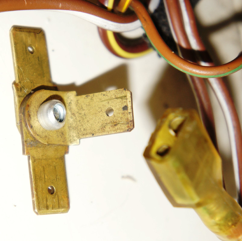
1. getting a decent shunt ready (see photo) for bridging the two 9.5mm spade connectors of the brown-white wires from the RHS terminals B-B (which are in fact common) once they?ve been disconnected from the regulator, I used three flat 9.5mm spades riveted together so I could also have a solid connection to an ammeter-wire for the Current Test.
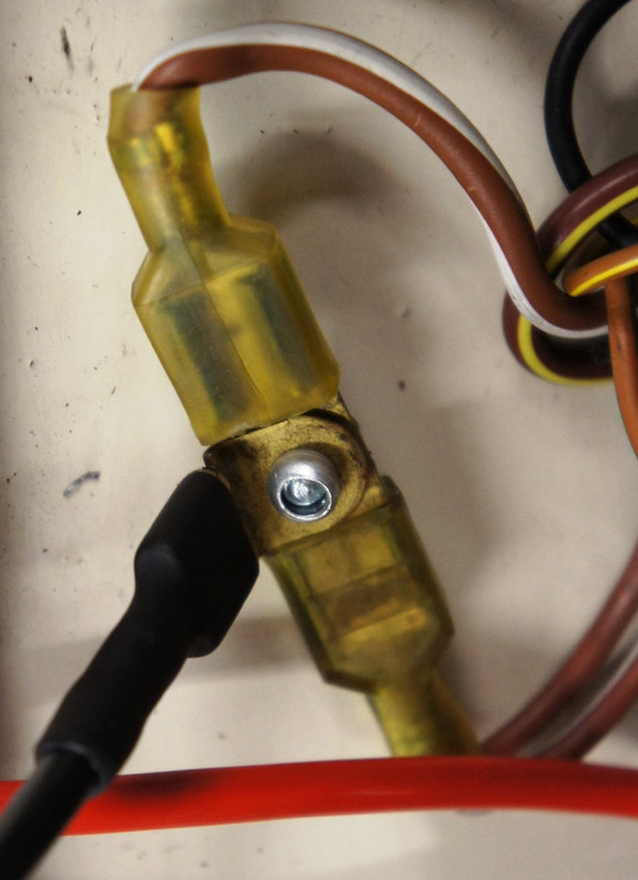
2. removing the brown/green off the W-L (Warning Light) spade, and replacing it with an insulated spade plus short wire to facilitate its connection to a voltmeter.
3. finding a way of holding an accurate moving-coil voltmeter on a clamp or w.h.y. so that it can be used hands-free.
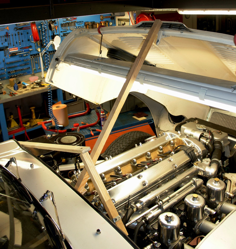
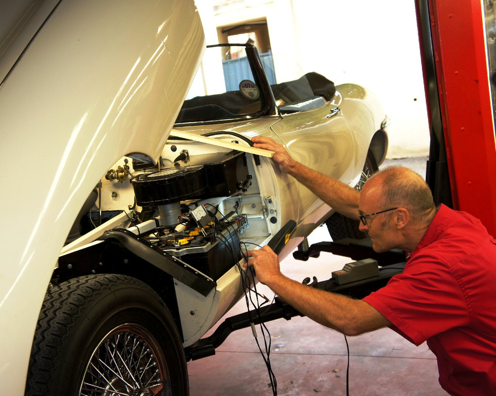
4. setting up some Heath-Robinson jury-rig so that the throttle can be operated from the regulator area - even if you have a second pair of hands and feet to help, I still think this was 15 minutes well spent, notwithstanding its disgraceful construction out of some scrap timber and a few dry-walling screws ; don't tell anyone I made this please.
I suspect that you can do these adjustments in whichever order you choose but like a good soldier I did them in the Lucas sequence.
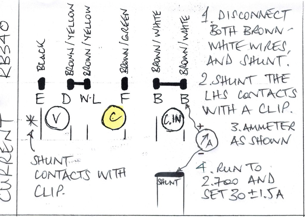
1. CURRENT - see Lucas Handbook pages 18, 19
This requires either an inductive clamp that will do DC or a serious industrial meter like this one I got for £15 on E-Bay :
http://www.ebay.co.uk/itm/AMMETER-0-40- ... 3f2c38b29b
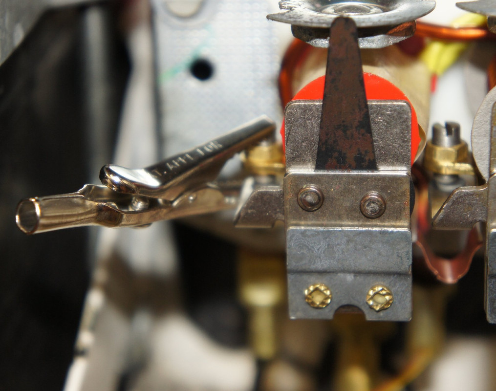
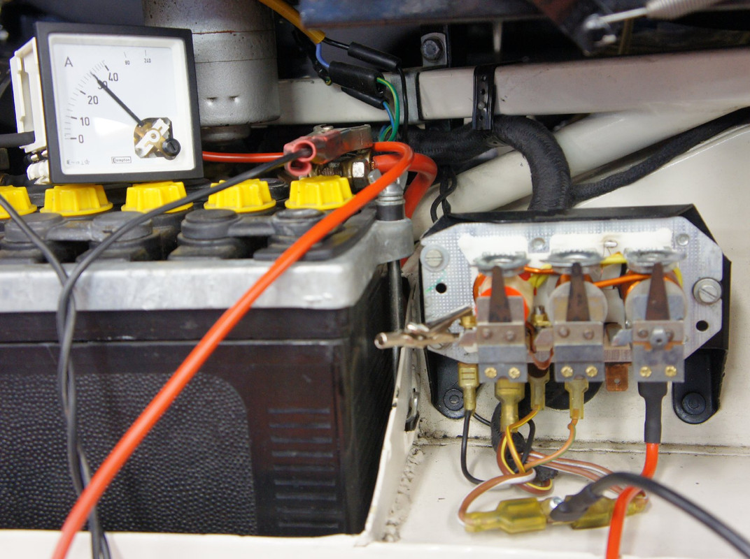
Use a crocodile clip to hold the points shut and bridged on the LHS/front of the RB340, and with the brown/whites disconnected from their B-B terminals and shunted together, connect them (via the shunt) to the -ve terminal of a 0-40 amp ammeter, and the +ve terminal of the ammeter to the B-B terminals on the regulator. Start the engine, switch the headlamps, panel lights, heater fan etc and run the dynamo up to 4.500 rpm (whatever engine rpm necessary for this, 2.700 for me) and check the maximum current - for the C42 used on my car this should be adjusted to 30A +/- 1.5A.
2. VOLTAGE CAM - see Lucas Handbook page 20
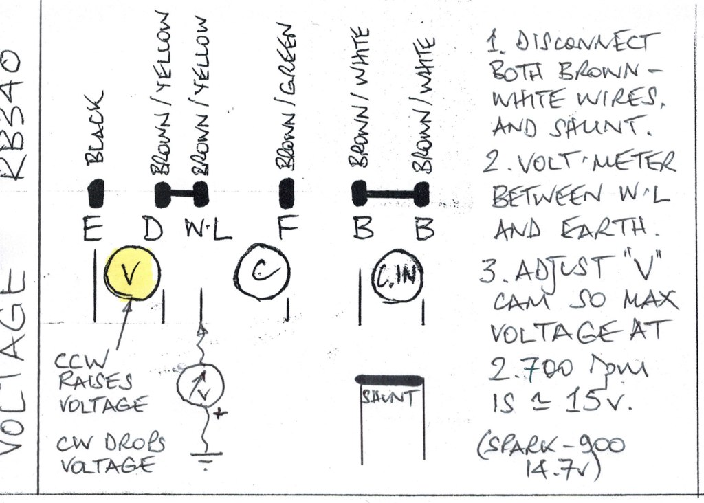
This determines the charging voltage seen by the battery. Once wired up as per diagram, run the dynamo to 4.500 rpm (2.800 engine rpm on my car) and set the cam so that the voltage is about 15v - on my car the cam adjustment is very sensitive at this point. There is a Lucas table of corrections for temperature, but essentially the tolerances are large and 15v is shown to be acceptable for temperatures ranging from 10°C up to 40°C ambient. If you've got an odd battery (I'm using a modern Spark-900) then you may need to adopt a different reading here, mine requires a maximum of 14.7v. From what I can see the revs are actually irrelevant once you have reached the peak - from about 2.000 engine rpm upwards the reading is stable on my car.
3. CUT-IN CAM - see Lucas Handbook page 23
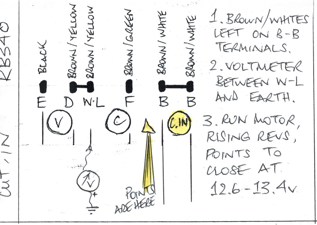
This is misleadingly labelled as a cut-out relay on some diagrams. First the brown/whites go back on their B-B terminals, and the voltmeter goes between the temporary wire on the W-L terminal and earth. Run the engine, then watch carefully the pair of contacts that are between bobbins C and C.IN (that's centre and right, of the three) - these points will start off open, then as the revs rise there will be a click and they will close. It is the voltage reading when they close that is critical - between 12.6 and 13.4v is correct. The C.IN cam is adjusted to obtain that reading - I just aimed for 13v. All the books talk about watching for a jerk in the volt-meter reading as showing the points closing, but I found this very hard to ascertain and the visual method was much more reliable.
4. DROP-OFF CONTACTS - see Lucas Handbook page 24
These are the same ones you've just observed when adjusting the Cut-In cam. Start by disconnecting the brown/whites from their B-B terminals, and connecting them together again with the shunt, as per for the Voltage Cam. Fit a voltmeter between the BB terminals and earth. Then rev the engine to about 2.000 rpm (should see 13 - 14v or so) and let the revs drop slowly ; the voltmeter reading should drop gently, then fall suddenly as the contacts open - this fall should occur at a value between 9.5 and 11v. The adjustment of this requires bending the fixed contact arm, I found that I could bend it just with pressure from a long insulated screwdriver ; pliers would be inviting shorting something out I fear. Reducing the air-gap will increase the drop-off voltage reading, whereas increasing the air-gap will reduce the voltage. I just aimed for 10v and found it quite easy to tweak the position with the screwdriver.
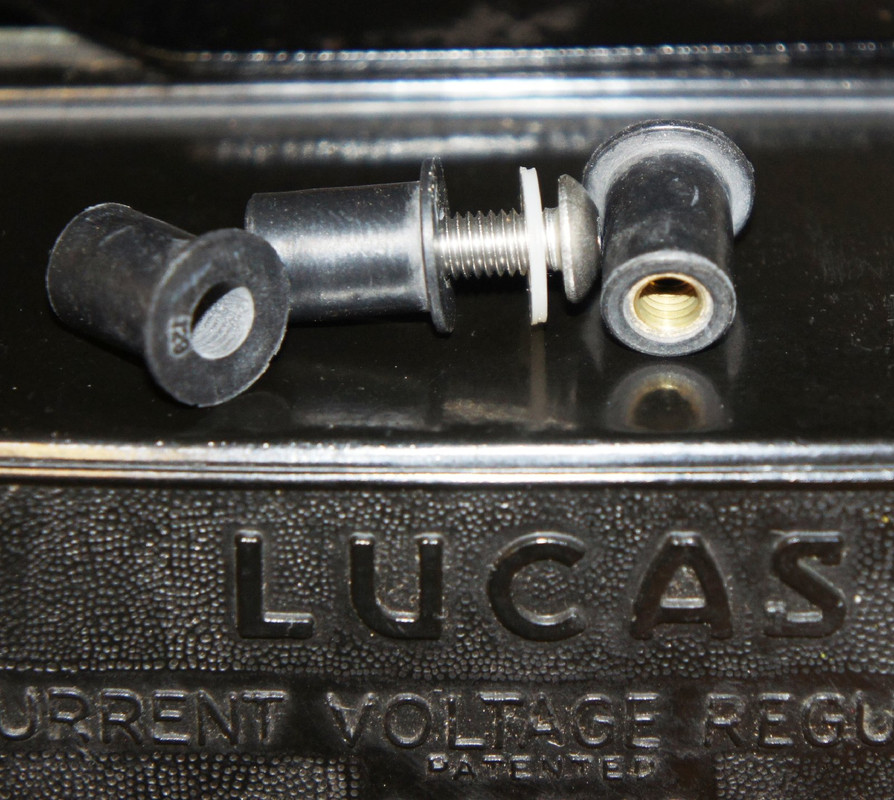
The cover on my car was held on by a two ghastly sort-of black nylon reusable pop-rivets, which I couldn't live with even if they were original - 5mm rubber Well-nuts require the back-plate holes drilling out to 9.5mm, and then you can use conventional screws ; I promise to replace the dome-headed Allens with something more "period".
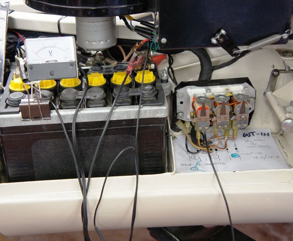 HERE ARE THE CARDS TO PRINT OUT THAT MAKE IT EASIER TO REMEMBER WHAT YOU'RE TRYING TO DO WHILST BEING ASPHYXIATED BY ENGINE FUMES AND DEAFENED BY THE EXHAUST NOISE :