All the following is from my '64 4.2 Coupe (rhd):
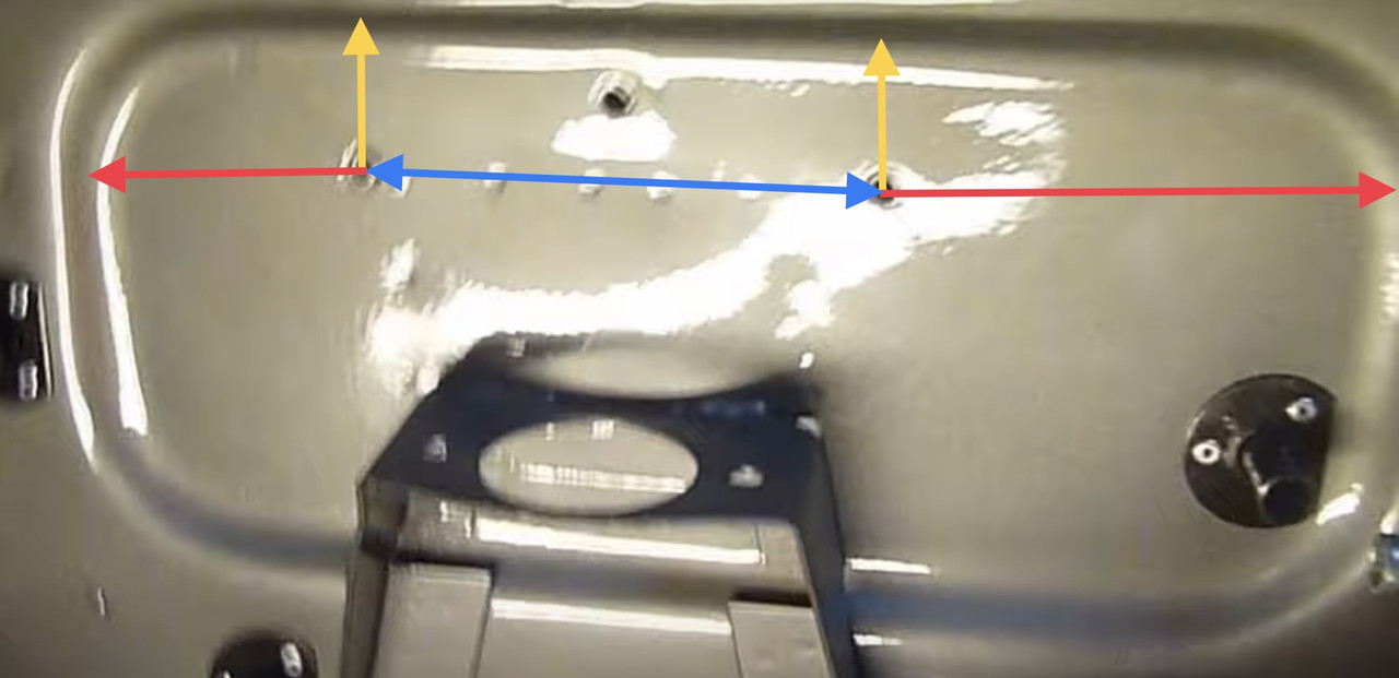
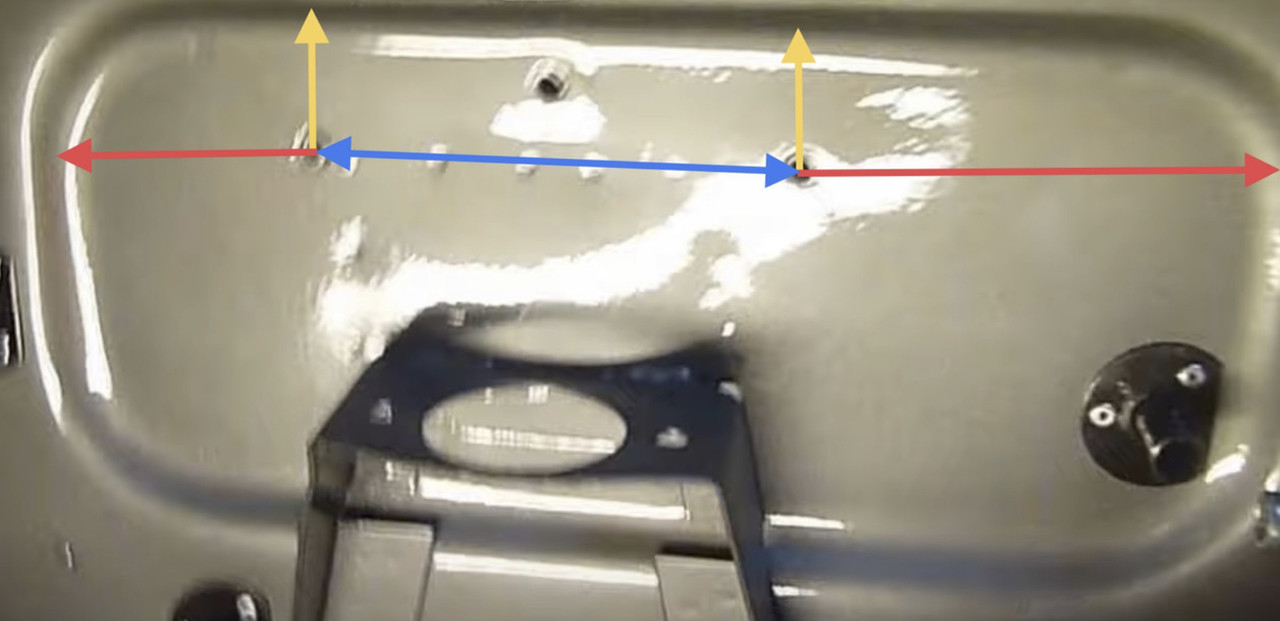
Approx. 5" centre-to-centre, and approx 1.5" down from the middle of the bend radius in the inset bulkhead panel.
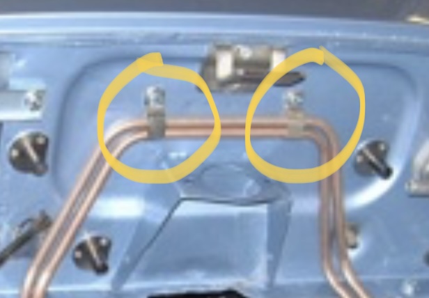
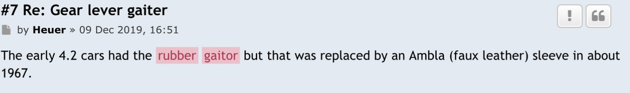
My pipes were zinc plated or galvanised steel (or some other silver coloured plating), not copper. One pipe at the vacuum tank side has a tee welded onto one end. IIRC the tee has a flexible vacuum hose attached that goes to the master cylinder diaphragm valve, the straight bit of the pipe has another flexible pipe that goes to the the vacumm tank non-return valve.
The other end of the pipes are strapped side-by-side underneath the diagonal tubular engine frame on the near side. Becasue the ends are partially hidden, It's very easy to get confused when connecting these pipes to the servo. If you get the pipes mixed up, the harder you apply the brakes, the harder the servo tries to un-apply them. Ask me how I know

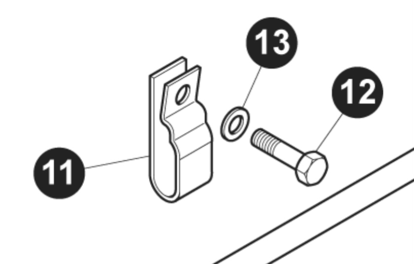
I made my own clamps.You can see at the top of the elongated oval part (for the vacuum pipes) has a smaller secondary bulge in it, which is for the master cylinder to servo transfer pipe. This pipe is a bit larger diameter than the rest of the brake pipes.
Hope this helps.