Talk about the E-Type Series 1
-
Topic author
ChrisC
- Posts: 1291
- Joined: Sun Feb 14, 2010 11:38 am
- Location: Surrey UK
-
Contact:

Post
by ChrisC » Mon Aug 01, 2011 11:47 am
Morning chaps.
Can anyone tell me how to take the indicator arm cover off? I want to give the whole thing a good clean and respray the visible parts...
It appears that the cover has a join but I am not a fan of using force when there might be screws or something that i cant see...
I havnt decided on what best to do about the actual arm which needs rechroming - by all accounts replacing it is not really an option... but I am open to suggestions
Cheers

-
Heuer
- Administrator
- Posts: 15204
- Joined: Sat Mar 01, 2008 5:29 pm
- Location: Nottinghamshire
Post
by Heuer » Mon Aug 01, 2011 11:55 am
Do you have the earlier cast alloy cover or the later plastic version? One half uses two spring clip (i.e. it is a push fit) retainers so you should be able to pull it off. The other half is held on to the column with screws. If you have the plastic version take your time with removal as the repro ones are horrible. You may find a previous owner has glued it on as they have an annoying habit of popping off when applying steering lock.

-
Topic author
ChrisC
- Posts: 1291
- Joined: Sun Feb 14, 2010 11:38 am
- Location: Surrey UK
-
Contact:
Post
by ChrisC » Mon Aug 01, 2011 12:10 pm
its definitely alloy. Thanks now that i know - it makes the use of a little force more acceptable...
-
265bhp
- Posts: 868
- Joined: Wed Jan 26, 2011 10:29 pm
- Location: surrey
Post
by 265bhp » Mon Aug 01, 2011 10:22 pm
chris
hope you dont mind but I have a related question regarding the locking ring to my car, which is a 63 FHC
as the photo shows, my locking ring is either a different design or its just missing the ribbed profiled profile....are the tiny holes in the funnel shaped rim for some kind of grub screw to hold the ribbed profile...what does anyone think...?
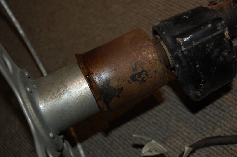
many thanks
Jonathan
-
Topic author
ChrisC
- Posts: 1291
- Joined: Sun Feb 14, 2010 11:38 am
- Location: Surrey UK
-
Contact:
Post
by ChrisC » Tue Aug 02, 2011 8:38 am
Looking at the ribbed ring - it looks like its sealed within a plastic coating (possibly paint or powder cost) but there are no apparent screws or clips. I certainly cant see a way to remove it from the main housing that you have.
-
265bhp
- Posts: 868
- Joined: Wed Jan 26, 2011 10:29 pm
- Location: surrey
Post
by 265bhp » Tue Aug 02, 2011 9:32 am
Hi Chris
Thanks for the reply....Bit of a mystery them :) ...maybe the plastic ring is bonded onto the metal ring or even moulded in situ, perhaps the holes I have then act as some kind of locking gesture to the plastic moulding to stop it slipping around the metal ring
Looks like I 'm on the hunt for a replacement then.... 8)
Regards
Jonathan
-
PeterCrespin
- Posts: 4561
- Joined: Fri Mar 05, 2010 8:22 pm
- Location: Gaithersburg, Maryland.
-
Contact:

Post
by PeterCrespin » Tue Aug 02, 2011 9:55 am
I think you're right. The body of the sleeve is pressed or spun I think, with the threaded boss fixed in the bottom and the knurled ring moulded in place around the rim. It would be too hard to press from a metal blank that thick, and too wasteful/expensive to machine that sleeve complete with knurled rim from a billet of steel or thick stamping.
As for replacing it, I pretty much just grab the sleeve anyhow when adjusting the wheel, so it should still be prefectly functional as-is. It's not exactly gonig to rip anyone's eyeballs out of their sockets as being a high-visibilty 'wrong' thing on the car. I'd probably run with it painted black and just casually keep a lookout for a cheapo correct part. You can tell any enquirers it's a 'works' weight-saving trick

PEte
1E75339 UberLynx D-Type; 1R27190 70 FHC; 1E78478; 2001 Vanden Plas
-
265bhp
- Posts: 868
- Joined: Wed Jan 26, 2011 10:29 pm
- Location: surrey
Post
by 265bhp » Tue Aug 02, 2011 11:54 am
Hi Peter
That sounds about right for the manufacture....the cars a full on resoration project so there's no real hurry....will keep a look out as you say, although the lightweight approach appeals too... 8)
Regards
Jonathan
-
kingzetts
- Posts: 745
- Joined: Thu May 15, 2008 9:33 am
- Location: Worcester UK
Post
by kingzetts » Tue Aug 02, 2011 1:53 pm
If you have access to a lathe I'd be tempted to knock up a "knurled ring" myself. Mix up some isopon in a shallow plastic round tray or saucer of an approriate size and stick the metal bit in it. When the filler has set, spin it up in the lathe and cut to the approximate size, then dremel a few knurls in it and slap on some paint.
But then I quite like silly little projects like that......just to see if I can do it! Good job I don't cost in my time, though.
John '62 S1 OTS (now sold)


