Steering Rack fail safes

Talk about the E-Type Series 1
User avatar

rfs1957
Posts: 1327
Joined: Sat Jan 15, 2011 2:52 pm
Location: Languedoc - France
France

#41 Re: Steering Rack fail safes

Post by rfs1957 » Mon Oct 09, 2023 2:48 pm

I'm sorry that Peter never got any Series-3 replies back in July 2020, regarding his rack query, and can't myself help.

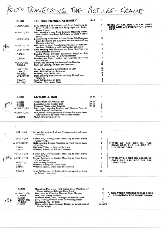
Much of the steam and hot-air could have been taken out of this subject if one of the protagonists had committed sketch-to-paper and laid out the various components so that the profane could have understood even just what the original assembly looked like, and in what order parts were assembled.

I feel zero shame in admitting that much of this question remains opaque for me, but I will learn fast, and intend to render it clear once and for all.

One aspect - a critical aspect - is "what length and diameter should the spacers be", and I have seen several different sizes being used.

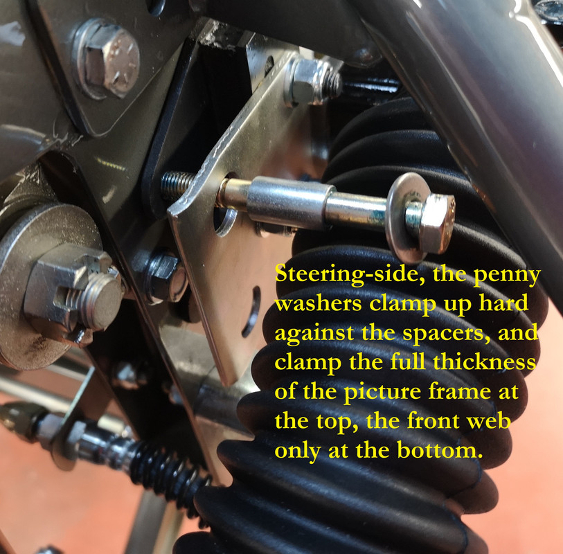
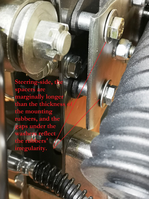
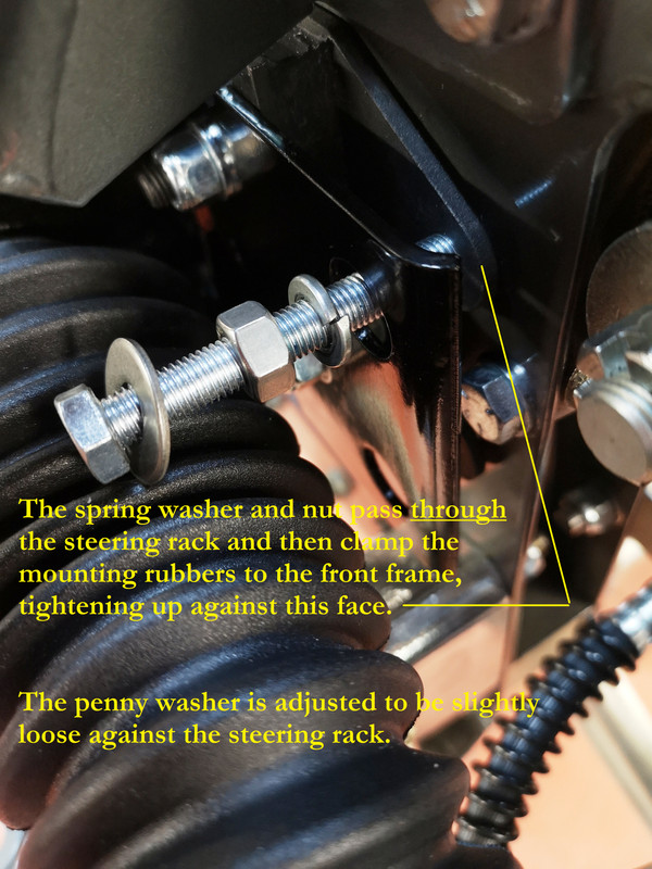
So, would some kind folk tell me what (if any) clearance/gap they have on the steering side, under the heads of the two safety washers ?

Image

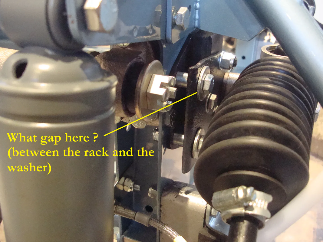
What kind of play did they find between the bush outer diameter and the hole in the rack ?

I have what purport to be the correct C18901 distance pieces, but they are 25mm long, which would set the safety washer about 7mm away from the face of the rack.

Image

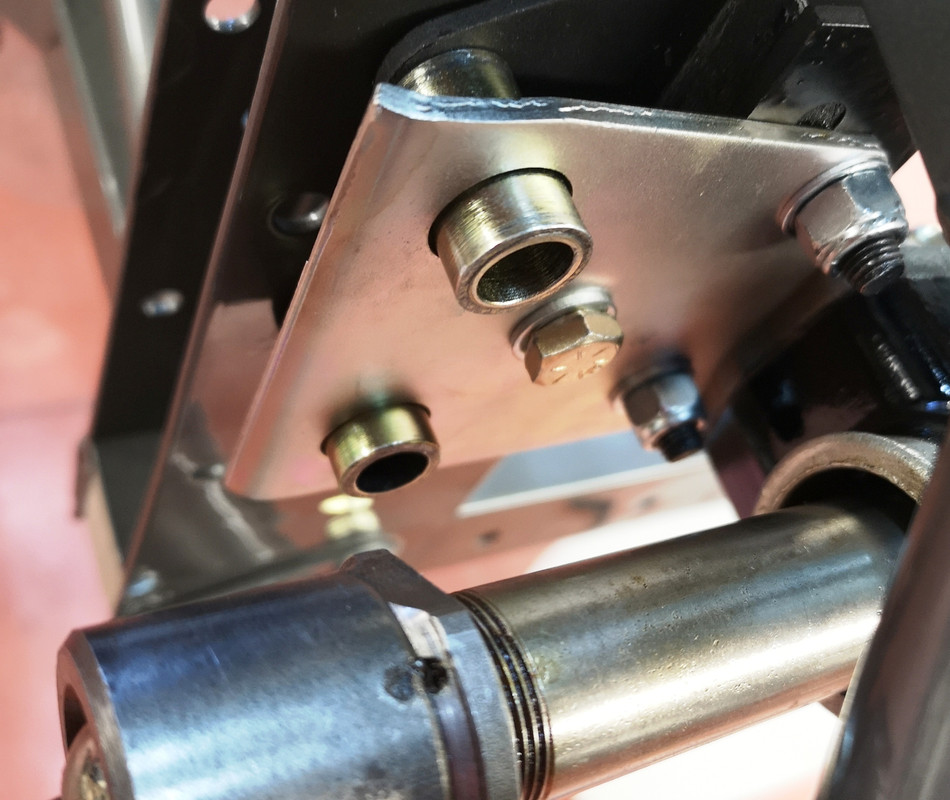
Same thing for the diameter - the big holes in my rack are about 16.90mm, and the spacer is about 16.10mm - which seems a pretty snug fit, and leaves not much room for quietening/cossetting my driving experience.

I think they’re wrong.

If anyone has access to parts of known provenance I would appreciate sizes.

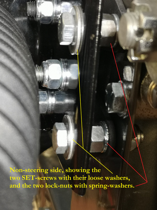
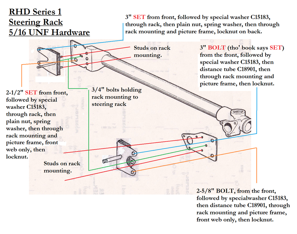
For those who feel they already have a phD in this topic, could you explain the choice by Jaguar, for the steering-column-side location, of a three-inch SETSCREW UFS.131/24R, threaded-to-head, rather than just a bolt, when the fastener chosen for its immediate neighbour is a straightforward BOLT - UFB.131/13R.

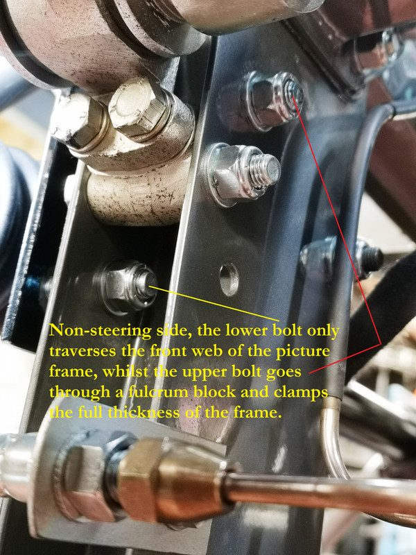
I get the use of UFS.131/24R and UFS.131/13R on the non-steering side, which requires adjustment, but not on the side that requires simple clamped-up spacers.

Is this a mis-print (rare ?) in the J30 parts book ?
Last edited by rfs1957 on Wed Nov 08, 2023 1:11 pm, edited 1 time in total.
Rory
3.8 OTS S1 Opalescent Silver Grey - built May 28th 1962

Link:
BBcode:
HTML:
Hide post links
Show post links

User avatar

mgcjag
Moderator
Posts: 8118
Joined: Fri Jul 09, 2010 6:15 pm
Location: Ludlow Shropshire
Great Britain

#42 Re: Steering Rack fail safes

Post by mgcjag » Mon Oct 09, 2023 7:04 pm

From the factory fit section...and from what iv seen and fitted your spacers sticks out too far....it could be your spacer or the mount thickness...as for gap behind the washer as per the service manual..just enough to be able to turn the washer with fingers as per other side but pinion side then tightened down onto the spacer...Steve
Image
Steve
69 S2 2+2 (just sold) ..Realm C type replica, 1960 xk150fhc

Link:
BBcode:
HTML:
Hide post links
Show post links

User avatar

rfs1957
Posts: 1327
Joined: Sat Jan 15, 2011 2:52 pm
Location: Languedoc - France
France

#43 Re: Steering Rack fail safes

Post by rfs1957 » Thu Oct 19, 2023 11:25 am

Yes Steve, indeed those spacers are way too tall and fat.

I’ve ordered the correct references from SNGB and Brian there has confirmed the dimensions.

I’ll put the sizes up with the pictures when I fit them.
Rory
3.8 OTS S1 Opalescent Silver Grey - built May 28th 1962

Link:
BBcode:
HTML:
Hide post links
Show post links

User avatar

rfs1957
Posts: 1327
Joined: Sat Jan 15, 2011 2:52 pm
Location: Languedoc - France
France

#44 Re: Steering Rack fail safes

Post by rfs1957 » Tue Nov 07, 2023 7:31 pm

Okay, FWIIW this is what I think I've understood, with some pictures that I am pretty confident are the translation of the Parts Catalogue J30 components into their actual context.

Again, I've invented nothing, but - and It's Because I Is Dumb - would have liked to have access to an explanation like this, in words of one syllable, when assembling my car.

The nuances regarding the provision for fail-safe mounting of the steering-rack are legion, and I suspect many cars are assembled incorrectly - for there is no drawing of this in any publication I have seen, and the references to it in the Workshop Manuals - even the original one - are very far from being clear, to me.

At least, they're clear when you understand how it works.

Essentially, Jaguar needed to make sure that if the rubber mountings failed then the driver did not lose the steering - the rack being essentially bonded to the car via the mounting blocks ; if the rubbers fail, the rack will cease to steer the wheels.

On the Series 1, Jaguar treated the issue slightly differently at each end.

I understand the provision changed on later cars.

On the steering-wheel side they made a provision using spacers (referred to as "distance tubes" C18901 in J30) and "special" washers (C15183) so that in the case of a failed rubber the steering rack remained constrained both laterally and fore-and-aft ; the components are bolted up tight, with inbuilt gaps sufficient to keep the rack effectively rubber-mounted.

Image

Image

As supplied by SNGB, the Distance Tubes are 19.70mm long, 11.00mm OD, 8.50mm ID.

The Special Washer is 20.00mm OD and 1.50mm thick, basically any penny washer will do the business.

On the non-steering side, the same "special" washers are used, but - for reasons that nobody seems clear about - without the spacers ; the washers are then adjusted, in fact, to remain slightly loose, by the use of a locking plain-nut and spring-washer in the middle of the SET screws (threaded to head) that fasten the rack in place on that side.

Image

Image

I found this surprisingly tricky to get right, as it really requires the use of three spanners on the same bolt.

Image

This stops the rack falling away from the rubber should it fail, whilst not unduly interfering with the intended suppleness of the mounting.

Image

Again somewhat unfathomably, Jaguar listed the same 3" SET screw for the upper fixation on both sides of these ensembles, when there is no sense or need for this on the steering-side, as a BOLT does the job just as well, or better.

Perhaps just for reasons of standardisation/rationalisation during assembly ?

It is very tempting to fit the spacers on all four mounting points, and thus duplicate the steering-wheel-side principle ; anyone who has done that might like to offer an opinion ?

Here's a diagram that might help.

Image

and here's the component spec as defined by J30, refer to the block taken from page 142.

Image

For a more complete breakdown of the Front Frame or Picture Frame fasteners, see here :

viewtopic.php?f=3&t=20365
Rory
3.8 OTS S1 Opalescent Silver Grey - built May 28th 1962

Link:
BBcode:
HTML:
Hide post links
Show post links

Post Reply Previous topicNext topic