#1 Turn signal and horn push assembly - small parts
Posted: Mon Sep 30, 2024 12:35 am
i took my turn signal assembly apart without taking a photo beforehand.
Now I have eleven small parts that I don't where they go. Any help would be appreciated.
They are:
A - two screws that go into what in I believe are two square slightly curved washers.
B - two small springs
C - one larger spring
D - two copper pieces similar in appearance to a staple.
E - one screw-in object that has a raised rail like section on its top
F - one threaded screw that appears to screw into the steering column to hold the metal strap that locks the white plastic holder from moving.
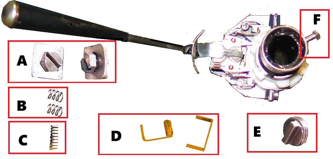
I found out that the two screws and two washers labeled as A go where I originally indicated F to go Now where does F go to ?
Now I have eleven small parts that I don't where they go. Any help would be appreciated.
They are:
A - two screws that go into what in I believe are two square slightly curved washers.
B - two small springs
C - one larger spring
D - two copper pieces similar in appearance to a staple.
E - one screw-in object that has a raised rail like section on its top
F - one threaded screw that appears to screw into the steering column to hold the metal strap that locks the white plastic holder from moving.
I found out that the two screws and two washers labeled as A go where I originally indicated F to go Now where does F go to ?