Wiper Motor switch diagram Series 2 2+2

Talk about the E-Type Series 2
User avatar

Topic author
Paul 012
Posts: 46
Joined: Fri Jun 29, 2012 8:25 pm
Location: Toronto, Canada

#1 Wiper Motor switch diagram Series 2 2+2

Post by Paul 012 » Mon Apr 08, 2013 8:36 pm

Image

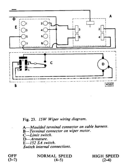
I received a new switch to replace the defunct switch, part # c33862. The new switch has 8 pins, the previous switch had 4 pins (possibly incorrect switch before?).

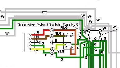
I have 4 wires in my harness to the wiper motor connector: they are RLG, ULG, G and YLG: I have continuity on all these wires from the switch end to the connector end. There is also a B at the connector which goes from the connector to the Wash bottle motor and from there to Ground.

All electrical diagrams (inc the original one in the owners package) show NLG in place of the ULG: as my harness is original, I am presuming (aah) that at some stage the NLG was replaced by a ULG and/or there was a constant typo along the way or there is discoloration of the wiring cover.
Also the numbering of the pins on the diagrams seems incomplete.

There is also a B ground shown on diagrams at the wiper switch but I did not have this on my switch when I removed it: it is not the B from the connector as this runs as described above.

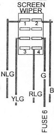
Below is a snap shot of the wiring diagram where pin 1 is NLG (my ULG), pin2 is B ground by cable, unspecified pin # for YLG, unspecified pin # for G, pin 4 is RLG and pin 3 is not used.

I have seen the set up on my colleagues Series 2 but I cannot verify pin numbers. His appears to go as follows: RLG on pin 2, ULG on pin 4, G on pin 5, YLG on Pin 7. There is no B ground wire at all on his switch.

Can anyone tell me the correct pins on this 8 pin switch to connect these 4 wires to plus the B ground.

Link:
BBcode:
HTML:
Hide post links
Show post links

User avatar

Heuer
Administrator
Posts: 15157
Joined: Sat Mar 01, 2008 5:29 pm
Location: Nottinghamshire
Great Britain

#2

Post by Heuer » Mon Apr 08, 2013 8:57 pm

Is your car a S1.5 US delivery circa 1968? Please check the wiper motor - is it a DL3A with three wires plus earth? Does the wiper motor have an adjustable Paxolin disc on the front?
David Jones
S1 OTS OSB
1997 Porsche 911 Guards Red
2024 Lexus LBX

Add your E-Type to our World Map: http://forum.etypeuk.com/viewtopic.php?f=1&t=1810

Link:
BBcode:
HTML:
Hide post links
Show post links

User avatar

Topic author
Paul 012
Posts: 46
Joined: Fri Jun 29, 2012 8:25 pm
Location: Toronto, Canada

#3

Post by Paul 012 » Mon Apr 08, 2013 9:56 pm

Definitley Series 2 (1970) US delivered (but now in Canada)

How do I check if it's a DL3A?

Paxolin Disc? I'll show my ignorance and ask what that is?

Wires from switch to cable are RLG, ULG, G and YLG but I'll get under the bonnet tonight to check

back to you shortly
Paul

Link:
BBcode:
HTML:
Hide post links
Show post links

User avatar

chrisvine
Posts: 363
Joined: Sun Jan 10, 2010 4:27 pm
Location: Windsor
Contact:
Great Britain

#4

Post by chrisvine » Mon Apr 08, 2013 10:39 pm

Paul,

The wiper motor on my S2 (late '69) is the Lucas Type 15W.

From the wiring diagram I'm using, the second row of pins on the 8-pin switch aren't used. The other connections are the same as your diagram:

Image

If you want the wiring diagrams, PM your email address.

Chris
1969 S2 OTS, Elise S1

Restoration Blog : http://etype.chrisvine.com/

Link:
BBcode:
HTML:
Hide post links
Show post links

User avatar

Heuer
Administrator
Posts: 15157
Joined: Sat Mar 01, 2008 5:29 pm
Location: Nottinghamshire
Great Britain

#5

Post by Heuer » Tue Apr 09, 2013 10:26 am

DL3A motor:
Image

This motor has three wires, the earlier DL3 motor has five wires as has the later 15W round motor. The DL3A motor was only fitted to LHD 1968 cars.
David Jones
S1 OTS OSB
1997 Porsche 911 Guards Red
2024 Lexus LBX

Add your E-Type to our World Map: http://forum.etypeuk.com/viewtopic.php?f=1&t=1810

Link:
BBcode:
HTML:
Hide post links
Show post links

User avatar

Topic author
Paul 012
Posts: 46
Joined: Fri Jun 29, 2012 8:25 pm
Location: Toronto, Canada

#6

Post by Paul 012 » Tue Apr 09, 2013 6:27 pm

Motor is the Lucas 15W with 3 wires showing.

I checked the wires at the switch and they are ULG, YLG, RLG, G
Tucked away under some other wires, I found a B not connected anywhere so am presuming this is my missing Ground. Might explain the switch not working.

I will try Chrisvines solution tonight but my ULG (blue light green) is still incorrect where the wiring diagram shows NLG (Brown light green). Cannot see an NLG connected to another switch by mistake.

The ULG does run directly to the connector which looks original and does not seem to have been tampered with. As this is a direct wire, I should have no problems using this in the place of the NLG.

More later and thanks everyone for chipping in with clarification.
Paul

Link:
BBcode:
HTML:
Hide post links
Show post links

User avatar

Topic author
Paul 012
Posts: 46
Joined: Fri Jun 29, 2012 8:25 pm
Location: Toronto, Canada

#7

Post by Paul 012 » Tue Apr 09, 2013 6:31 pm

Clarification:
my connector has 5 wires at the switch.
The 3 wires I put in my previous post are exposed on the Lucas 15W motor

Link:
BBcode:
HTML:
Hide post links
Show post links

User avatar

chrisvine
Posts: 363
Joined: Sun Jan 10, 2010 4:27 pm
Location: Windsor
Contact:
Great Britain

#8

Post by chrisvine » Wed Apr 10, 2013 10:41 am

Paul,

Your query got me thinking I ought to check how I've wired my motor. My switch is a 4-pin so I think it is correct. The four pins are still labelled as though it were an 8-pin switch, ie the four pins with spade connections are 2, 4, 5 and 7.

Here's a much better wiring diagram for the switch and motor connections, so ignore the one in my post above:

Image

My wiring loom also has ULG wires rather than NLG so I suspect the wiring diagrams are incorrect.

In the above diagram, for connector A, the terminals are:
1 - B
2 - RLG
3 - YLG
4 - G
5 - ULG

If you've got an electronic multi-meter you should be able to set to continuity mode and confirm pins 5 & 7 are connected when switched to OFF, 4 & 5 when Normal and 2 & 4 when Fast.

Chris
1969 S2 OTS, Elise S1

Restoration Blog : http://etype.chrisvine.com/

Link:
BBcode:
HTML:
Hide post links
Show post links

User avatar

Topic author
Paul 012
Posts: 46
Joined: Fri Jun 29, 2012 8:25 pm
Location: Toronto, Canada

#9

Post by Paul 012 » Thu Apr 11, 2013 3:35 pm

Chris
I did try your first diagram last night and no luck, in fact after trying this with no result, I thought I should do my weekly engine run and got nothing to turn at all! Battery is fully charged so another issue to resolve.

Anyway, back to the original question.

By your second diagram, there is no ground at the switch (possibly why there was no B connected in the first place).

I'll give this new set up a go tonight if I can get work out the other issue!

Appreciate your guidance (as well as everyone else's)
Paul

Link:
BBcode:
HTML:
Hide post links
Show post links

User avatar

Topic author
Paul 012
Posts: 46
Joined: Fri Jun 29, 2012 8:25 pm
Location: Toronto, Canada

#10

Post by Paul 012 » Mon Apr 15, 2013 5:31 pm

Lack of starting was a loose battery cable. Car was running yesterday!

More importantly, some success with the wiper motor; the 2nd wiring diagram suggested by Chrisvine (many thanks) got me a single speed on the motor so I think we are on the right road. :D

I did not have time last night to check the switch and need to get the multi meter on this: I may have messed up a connector trying the other ways so will tackle that tonight.
Very happy with getting some movement.
Paul

Link:
BBcode:
HTML:
Hide post links
Show post links

User avatar

Heuer
Administrator
Posts: 15157
Joined: Sat Mar 01, 2008 5:29 pm
Location: Nottinghamshire
Great Britain

#11

Post by Heuer » Mon Apr 15, 2013 5:41 pm

Paul

If you have a three wire motor try connecting it up the same way as used by the DL3A motor. The DL3A motor works by being permanently live with the ignition on. The switch controls the earth to complete the circuit, almost counter intuitive. Also there are two 'earths' (plus the body). For slow speed both the green/red and the green/brown are switched to earth. For fast speed only the green/brown is switched to earth - the green/red is disconnected.

To get it to work with a earlier/later six pole switch however you need to connect as follows:

Motor Green to Loom Green
Motor Green/Red to Loom Green/Brown
Motor Green/Brown to Loom Green/Red

You may have to swap the last two around to get the speeds in the correct order.
David Jones
S1 OTS OSB
1997 Porsche 911 Guards Red
2024 Lexus LBX

Add your E-Type to our World Map: http://forum.etypeuk.com/viewtopic.php?f=1&t=1810

Link:
BBcode:
HTML:
Hide post links
Show post links


osgii
Posts: 346
Joined: Sun Aug 14, 2011 9:29 am
Switzerland

#12

Post by osgii » Wed Feb 11, 2015 12:50 pm

I'm actually also facing an issue with this damned DL3A motor... Because cable colors which run from the center facia panel to the engine compartment does not fit any wiring diagram. Don't have any color with brown, but a cable with light green and blue (as Chris stated). Also Yellow / Light Green if I remember well. And black, don't ask me why.

There is only tree cables coming out of the motor, but colors are faded with time (http://www.grainedevie.ch/restaurations ... 117745.jpg )

I'll try again during the week with:

Light Green & Red -> motor Light Green & Red
Green -> Light Green, or something that looks like Beige / Yellow ;)
Light Green & Blue -> the last one, which is a kind of Brown & White

And here is how my switch used to looks like:
http://www.grainedevie.ch/restaurations ... 021671.jpg

So the black is easy. Then i'll put the light green back in place, and the Light Green& Blue at the same place as the Light Green & Brown used to be.

I'll report if it works, maybe it will be helpful for someone.

Can someone tell me why I have two Red & Light Green coming trough the bulkhead, and only one cable to connect to the switch? It was the same configuration with the original harness.
1E35547

Link:
BBcode:
HTML:
Hide post links
Show post links

User avatar

chrisvine
Posts: 363
Joined: Sun Jan 10, 2010 4:27 pm
Location: Windsor
Contact:
Great Britain

#13

Post by chrisvine » Wed Feb 11, 2015 2:21 pm

The wiring diagrams above are for the round bodied 15W motor below:

Image

I think the DL3A motors have different wiring and the wiper parking switch was external to the motor.
1969 S2 OTS, Elise S1

Restoration Blog : http://etype.chrisvine.com/

Link:
BBcode:
HTML:
Hide post links
Show post links

Post Reply Previous topicNext topic