I recently sent my tacho to Richfield Speedograph for repair and it was returned "upgraded"
In the meantime (and whilst it was disconnected) I noticed that whilst the car would start immediately it would then stop immediately. I wrongly misdiagnosed this as an ignition problem and rushed into installing a SNG electronic ignition conversion. I then found that I had no feed to the coil.......
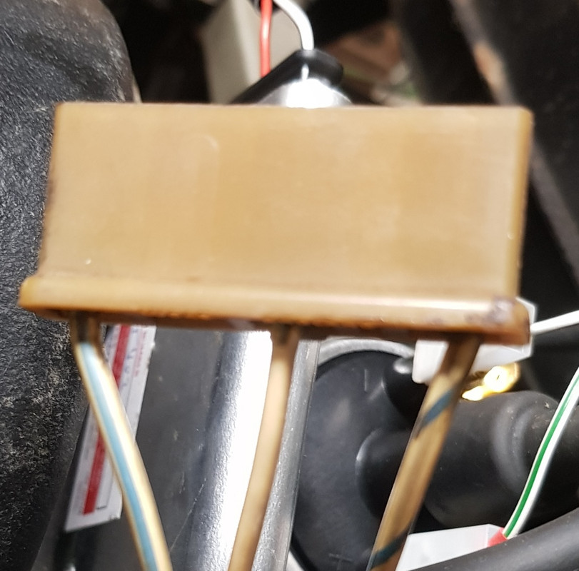
Having found a previous thread on this subject I now understand that the two white wires in 4xconnector block (now disconnected as per pic) behind tacho are instrumental in the supply to the coil.
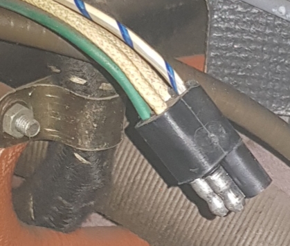
Speedograph Richfield say I must connect the green feed to the green in the taco and the blue/white in the tacho to the coil -ve. In the previous thread Marek said the white/diagonal blue wire can be repurposed and use it to connect to the coil -ve. Does he mean the white/diagonal blue wire (as shown in second pic) that goes into the pale plastic socket that is plugged into the (old) ballast resistor? ie I cut the wire and connect it to the
coil -ve?
Secondly, in order to restore supply to the coil what do I do with the two white wires in the connector block...simply connect them together?
OMG that was boring and long winded!
Has anyone followed that who can help me? I really don't want to ruin my tacho or electronic ignition!!!
David