


series 3 pcv questions

#1 series 3 pcv questions
Hello, I am trying to understand the pcv system on my 1973 series 3 e-type. This is USA spec.I have started at the crankcase vent with the conical screen. I cleaned it and proceeded to follow the breather pipes and cleaned them. At the juncture where they are connected to the curved hoses to the strombergs (4 hose attachments) there is a reduction in diameter at the end of the metal breather pipes at each attachment to the hose. I assume this is a metering device for crankcase ventilation? As I follow the metal pipes and this is LHD there is a 90 degree metal pipe extension at the front stromberg A-bank that has a metering port? with a brass port and conical mesh screen. This evidently connects to a hose and then to another breather hose #C34929 which is no longer available that connects where? Trying to understand this system? It evidently connects to the crankcase? Any clarifications would be most helpful. Best Regards
| Link: | |
| BBcode: | |
| HTML: | |
| Hide post links |

#2 Re: series 3 pcv questions
The extra stub would probably have connected to the carbon canister and been part of the fuel tank venting system. You can simply leave it plugged if it is not needed for that. The Feb1974 Parts Manual and tan coloured Owners Manual will explain all of the possible vacuum connections.
kind regards
Marek
kind regards
Marek
| Link: | |
| BBcode: | |
| HTML: | |
| Hide post links |
#3 Re: series 3 pcv questions
Great ....got it....I still Have the carbon canister in situ. I will check out the lines..Thanks again
| Link: | |
| BBcode: | |
| HTML: | |
| Hide post links |


#4 Re: series 3 pcv questions
Mine is/was same, ’72 US spec. I don’t have the tan manual (how to get it?) but I’ve studied the system, imo its pretty good, simple and effective. Here is how I think it works:
Crankcase ventilation is suction only, removing fumes that blow by the piston rings. I.e. there is no fresh air inlet to the crankcase. Suction is from the carburettors, upstream of the throttle plates. I.e. it is not manifold vacuum, it’s barely below atmospheric. I.e. the system does not compromise your manifold vacuum (as I once thought).
Fumes from the crankcase are sucked into the carburettors, I guess not much when the throttles are closed (idling), but not much blow-by then either.
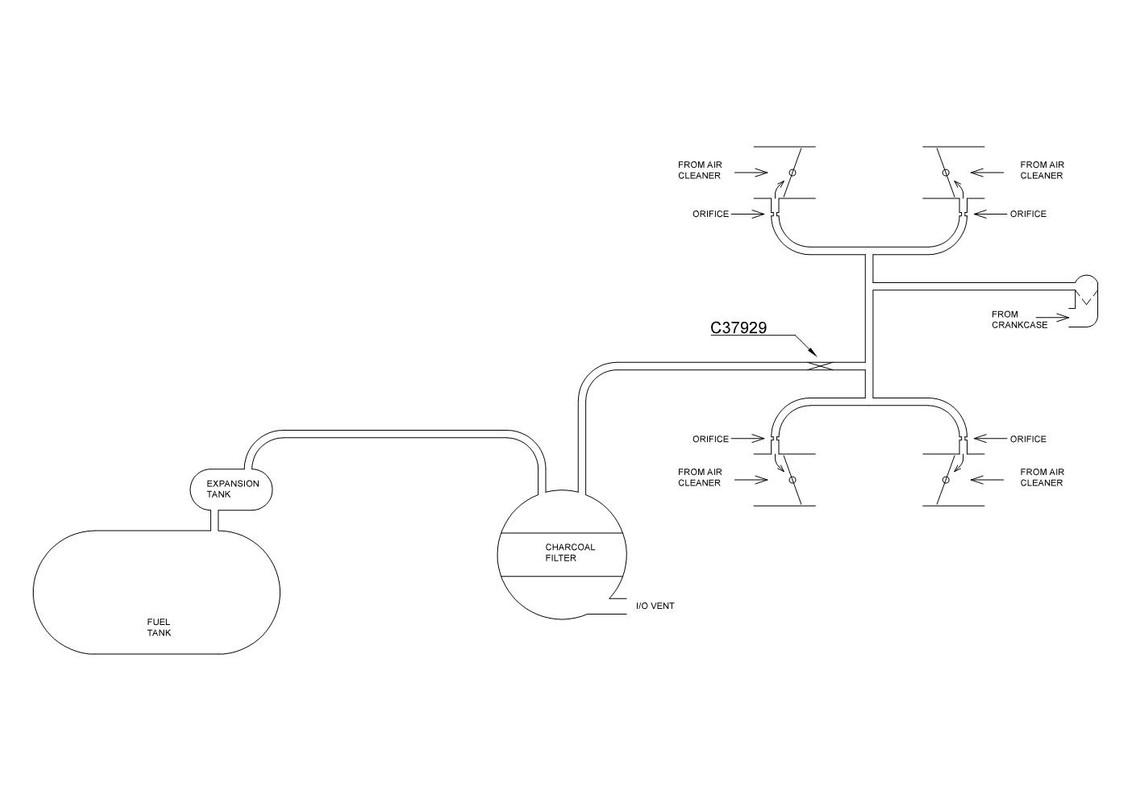
The “metering devices” that you refer to, shown on the diag. as “orifices”, I’ve always imagined that these are how the system was crudely calibrated/balanced so that flow was not all through one carb.
The same system is used to purge the charcoal canister. The I/O vent lets air in and out as the fuel level rises and falls or expands/contracts, the fuel is trapped by the charcoal. When the engine is running, air that is drawn into the I/O vent and through the charcoal by the carburettor suction effectively cleans the charcoal, transporting the trapped fuel into the carburettors.
Also shown on the diagram is the C37929 “vent valve”. My assumption is, this is set to restrict the rate of air that is drawn into charcoal canister (I/O vent) by the carbs, as necessary to ensure that there will always be positive ventilation of the crankcase.
Crankcase ventilation is suction only, removing fumes that blow by the piston rings. I.e. there is no fresh air inlet to the crankcase. Suction is from the carburettors, upstream of the throttle plates. I.e. it is not manifold vacuum, it’s barely below atmospheric. I.e. the system does not compromise your manifold vacuum (as I once thought).
Fumes from the crankcase are sucked into the carburettors, I guess not much when the throttles are closed (idling), but not much blow-by then either.
The “metering devices” that you refer to, shown on the diag. as “orifices”, I’ve always imagined that these are how the system was crudely calibrated/balanced so that flow was not all through one carb.
The same system is used to purge the charcoal canister. The I/O vent lets air in and out as the fuel level rises and falls or expands/contracts, the fuel is trapped by the charcoal. When the engine is running, air that is drawn into the I/O vent and through the charcoal by the carburettor suction effectively cleans the charcoal, transporting the trapped fuel into the carburettors.
Also shown on the diagram is the C37929 “vent valve”. My assumption is, this is set to restrict the rate of air that is drawn into charcoal canister (I/O vent) by the carbs, as necessary to ensure that there will always be positive ventilation of the crankcase.
Regards,
ColinL
'72 OTS manual V12
ColinL
'72 OTS manual V12
| Link: | |
| BBcode: | |
| HTML: | |
| Hide post links |

#5 Re: series 3 pcv questions
I had to disassemble the pipes connecting the carburetors to the crankcase ventilation. There are no ' orifices´or ´metering devices´ as one would expected, the whole pipe from crankcase to the Strombergs is about 8 mm internal diameter.
On the A bank, the rubber elbow connectors to the carburetors had a 5 mm hole venting the carburetor to the atmosphere. The upper part, to the crankcase metal pipe, was blocked by a ball from a bearing. Only on the right side.Courtesy of a previous owner, as rightly suggested by Marek. Purpose unknown.
I have installed new elbows, but the car developed a ´sinusoidal´behaviour when idling , with rpm increasing, then decreasing, the amplitude increases until it then stops. I kind of understand this: increased rpm, more blow-by gases, incrased rpm, then mixture gets leaner , rpm drop, gets richer again and the cycle goes on.Or so i see it . It seems that a damper effect is needed exactly through a constriction somewhere to stabilize the flow. But I see no signs of it .
I called SNG and the elbow connectors have constant 8mm internal diameter ...
Any clue?
Many thanks
Rui
| Link: | |
| BBcode: | |
| HTML: | |
| Hide post links |
#6 Re: series 3 pcv questions
This is what Rui is referring to:-
https://forums.jag-lovers.com/t/strombe ... -s3/431952
Since trying to set it up correctly gives a hunting idle, I would first ask whether all four carburettors are the same specification (and with the same needles and the same gap on the throttle plates and the same jet height etc) and after that, how it is that one side appears to have a different air bypass requirement to the other side? Assuming these are identical carburettors, I'd look for a blockage on the modified side, either because something else like the temperature compensators (which bypass air past the throttle plate) or some of the air routes inside the carburtettor on that side are more blocked/constricted by comparison to the good side. These four elbows are linked and so are acting as a balance pipe - but clearly one side is not balanced compared to the other.
kind regards
Marek
| Link: | |
| BBcode: | |
| HTML: | |
| Hide post links |
#7 Re: series 3 pcv questions
Indeed Marek, very well observed as usual :-)
All the carbs are the same, but as I reported some time ago I do have a problem of over rich mixture on the A bank, with the spark plugs fouling mostly when idling while in the B Bank spark plugs are always nice. And I can't set the mixture any leaner on the A Bank.
Dismantling A bank carbs is on the pipeline ... for a long time now. ( I kind of put on old conversion to injection as I fear problems at the technical control every two years, for engine modifications)
( Sunday i checked CO2 levels with the new elbow pipes on and it is still up to 8-9% with all needles down and B bank pugs nice beije , bank A fouled)
This is all the work I have done some time ago just to conclude carbs A bank need to come out:
https://forums.jag-lovers.com/t/v12-e-t ... ruimeneses
Temp compensators on the ´external carburetors´ were checked and adjusted for the right temp opening.
Many thanks again for you expert help !
Rui
| Link: | |
| BBcode: | |
| HTML: | |
| Hide post links |
#8 Re: series 3 pcv questions
Other than there being a problem with the jets/needles, perhaps the choke disc on the A bank is corroded and lets fuel through regardless of setting. Too much fuel is a reason why the previous owner made sure more air got through. It'd be most obvious at idle. Air and fuel are clearly mismatched, but without observing how one side differs from the other, I think it is very difficult to diagnose an obvious reason why.
kind regards
Marek
| Link: | |
| BBcode: | |
| HTML: | |
| Hide post links |
#9 Re: series 3 pcv questions
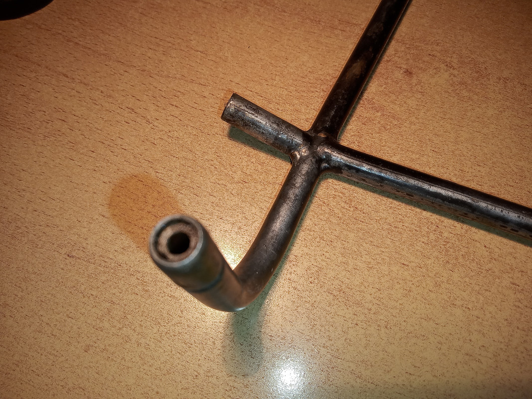
Here is photo of one of the orifices I was referring to. Orifice diameter is 3.7 mm.
Regards,
ColinL
'72 OTS manual V12
ColinL
'72 OTS manual V12
| Link: | |
| BBcode: | |
| HTML: | |
| Hide post links |
#10 Re: series 3 pcv questions
Indeed Marek, too rich fuel on the A Bank when idling - but I had previously ruled out the choke during previous tests as I had disconnected the pipe connecting the chokes on the 2 carbs and still spark plugs in all A-Bank cylinders were fouling and no change to CO2 levels.
Only one thing to do: carbs out ... better after the Summer. And the airflow between Banks is now certainly wrong as the previous settings were done with the large air leaks on the elbows of the carbs in bank A.
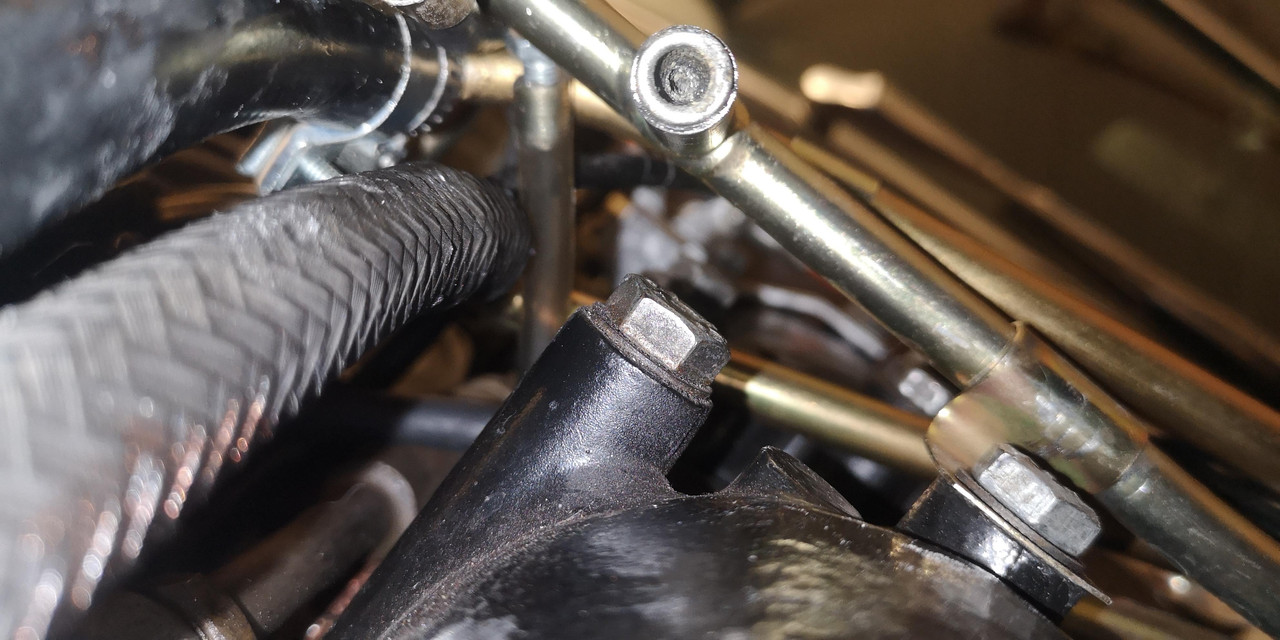
Colin, mystery solved, many thanks for your photo: I just come form the garage and disassembled the metal pipe to the carburetor elbows and the restrictors are there. i did not see them before because i expected the orifices to be quite smaller.
One last curiosity: On the pipe connecting to canister I had the filter C13457 for the earlier models instead of the C37929 restrictor (?) which is not available any longer (photo catalogue parts) C13457 still shows in SNG as Conical Brass oil gallery Filter serving Hydraulic tensioner (!!!).
Many thanks !
Rui
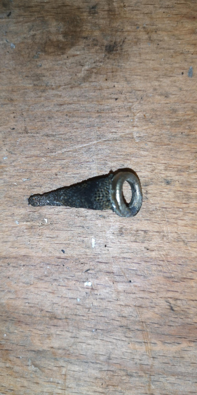
Above , with the small clogged filter still in place

Only one thing to do: carbs out ... better after the Summer. And the airflow between Banks is now certainly wrong as the previous settings were done with the large air leaks on the elbows of the carbs in bank A.
Colin, mystery solved, many thanks for your photo: I just come form the garage and disassembled the metal pipe to the carburetor elbows and the restrictors are there. i did not see them before because i expected the orifices to be quite smaller.
One last curiosity: On the pipe connecting to canister I had the filter C13457 for the earlier models instead of the C37929 restrictor (?) which is not available any longer (photo catalogue parts) C13457 still shows in SNG as Conical Brass oil gallery Filter serving Hydraulic tensioner (!!!).
Many thanks !
Rui
Above , with the small clogged filter still in place
| Link: | |
| BBcode: | |
| HTML: | |
| Hide post links |