Page 1 of 1
#1 Engine lifting frame
Posted: Fri Feb 19, 2021 9:44 am
by Fspp369
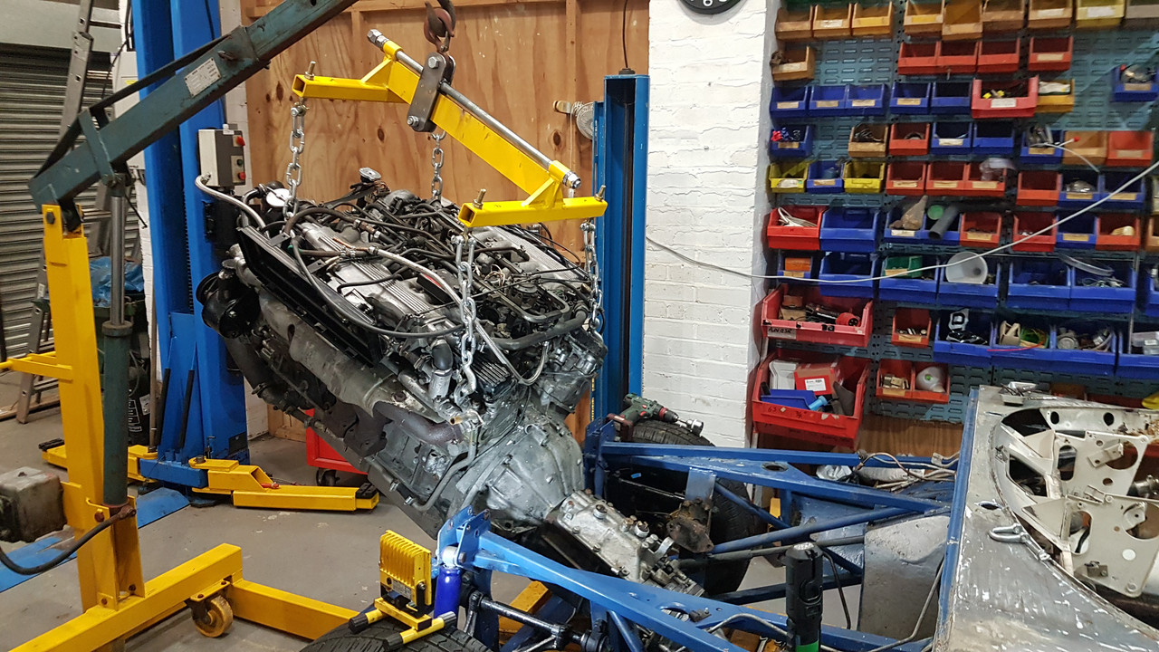
If anyone is interested a few pics of the V12 coming out with the new frame I constructed to try and minimise the scratching and gouging I’ve seen happen with other frames.
Continuing the theme “YOSTBTBDO.”

It all started with a bit of bodywork being chipped!
Peter

#2 Re: Engine lifting frame
Posted: Fri Feb 19, 2021 11:35 am
by vee12eman
Hi Peter,
Looks good, do you have any drawings or dimensions so we can replicate it?
Regards,
Simon.
#3 Re: Engine lifting frame
Posted: Fri Feb 19, 2021 11:57 am
by AussieEtype
I am sure using the leveling bar is a great help but over the years I have had my engine in and out of the car quite a few times and I have always just used four chains. The workshop manual lists the required length of the front and rear chains and using them the engine and gearbox is at the optimum angle for removal and installation - though care is needed not to lift the engine too high as the weight can topple the lot over.
Cheers
Garry
#4 Re: Engine lifting frame
Posted: Fri Feb 19, 2021 9:37 pm
by 71 V12
An engine load leveller does make the job a lot easier as you need to gradually steepen the angle of the engine and box as you extract the unit to clearthe bulkhead/ engine frames.
I use this:
https://www.machinemart.co.uk/p/cll500- ... lsrc=aw.ds
#5 Re: Engine lifting frame
Posted: Sat Feb 20, 2021 8:38 am
by Fspp369
I have a similar type of frame but almost all lifting frames end up having to angle chains in across the top of the engine scraping across alloy or worse fuel systems, particularly in my case with an Efi engine.
Hence I produced one that doesn’t do this.
The angle an engine and box combo has to achieve in order to be removed from an S3 car, without damage, is quite high..(not sure if this is the same for S1 and S2 )
#6 Re: Engine lifting frame
Posted: Sat Feb 20, 2021 9:22 am
by Fspp369
If anyone wants to make their own...
All materials steel unless specified.
The longitudinal beam is 75x15 mm As are the bracing segments.
The transverse frame is 30 x 5mm wall.
The chain is 2ton rated. So are the hooks.
The thrust bearings are from Amazon in this case 22mm bore.
The small eyes for chain attachment are to suit whichever chain shackles you use.
The “winding” rod M20 fine zinc plated.
The central nut is elongated full nut zinc plated.
The main lifting mechanism is 60x 5mm steel, with 2x HDPE sliding pads copper riveted to the 60/5, at the bottom are a pair of rollers inside each other to form a large diameter rolling bearing to run on the underside of the main beam...the sizes are dependent on the spacing required.
You will need a descent welding kit to assemble.
The static frame is shot blasted, powder coated “crane yellow” Central mechanism not coated just in case modification is required....so far none!
The whole engine can be tilted by HAND ROTATION of the end nuts. Total cost about £65
Hope that helps, can send video of operations if required.
Peter
#7 Re: Engine lifting frame
Posted: Sat Feb 20, 2021 10:16 am
by Bob.
Fspp369 wrote: ↑Sat Feb 20, 2021 8:38 am
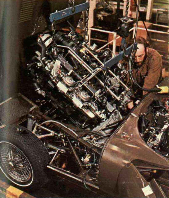
The angle an engine and box combo has to achieve in order to be removed from an S3 car, without damage, is quite high.
Going in too - in the factory early in production with bonnet already fitted. There appears to be a temporary Butec interference pad in the bonnet bulge.
#8 Re: Engine lifting frame
Posted: Sat Feb 20, 2021 11:23 am
by malcolm
Wonder why they'd do that with the bonnet on? I didn't find it difficult taking the bonnet off, and it must make the job easier.
#9 Re: Engine lifting frame
Posted: Sat Feb 20, 2021 4:55 pm
by Fspp369
Talk about making life difficult...