


1973 S3, air condition.
Hi.
My aircon fan switch is misbehaving and need fixing or replacement. But how are the switching sequence of this switch? Looking at the EL diagram its obivious that at position 1, you will have energized 1 terminal out of the swith to energize a/c thermostat switch, a/c radiator fan relay and a/c fan through a/c fan resistor.
Position 2 sends electricity at midpoint of resistor ( speeds up fan ).
I believe position 1 out of switch still needs to be energized otherwise thermostat switch and relay would also receive reduced current and / or overload the resistor.
Can anyone confirm this or put me right?
Same with pos 3, pos 1 also energized for same reason. In this case what about pos 2, also energized? Or does it matter?
Rgds Harald.
Air condition
-
 Ole-xke1974
- Posts: 181
- Joined: Sat Nov 08, 2014 9:52 am
- Location: Holmfirth, West Yorkshire

#2 Re: Air condition
Hi Harald,
that is a known problem with the S3 AC switch.
All current for the fan runs through the switch and when corrosion over 40+ years build up, you get poor connection and therefore heat build up. The heat causes the cam wheel inside the switch to melt and eventually the switch fails.
I believe Dick Wells in the US is working on a replacement. You can find him on Jag lovers forum.
https://forums.jag-lovers.com/
PS: I managed to refurbish the cam wheel with epoxy and use three mini relays to handle the currents.
Here's a link to the thread:
https://forums.jag-lovers.com/t/do-the- ... /392781/23
Good luck ...... Ole
1974 SIII E-Type w. XJ S2 4sp w. O/D
| Link: | |
| BBcode: | |
| HTML: | |
| Hide post links |
#3 Re: Air condition
Thanks for tips. Have not yet had time to look at it, but getting onto it in a couple of days. I was also planning on using relays to handle the current once I get the switch sorted out. It sits in a confined space and with relays, thin wires and tiny contacts can be used. And easing strain on switch. I have several replacement switches ( from other applications ) I will be looking at if I am not able to refurbish original switch. I’ll post the result.
Rgds Harald.
Rgds Harald.
| Link: | |
| BBcode: | |
| HTML: | |
| Hide post links |
#4 Re: Air condition
Hi Ole.
Have studied your post at jag-lovers with ac switch el. diagram. Capacitor and resistor, are they really necesary? I understand why you put them in there, but does it really matter if the «low» terminal is deenergized for a split second when changing to «medium» or «high». Yes you will save a switching cycle of ac fan relay and ac fan, ( the latter is switching to higher current anyway ) and maybe the compressor electric clutch depending on whether it is engaged or not when you are switching.
One of the switches I have is a four position switch with: off / 1 / 1 & 2 / 1 & 2 & 3. ( without deenergising 1 when switching ). Does 2 / medium need to be deenergized when using 3 / high? I can achive that by using an extra relay, but is it necesary?
Harald
| Link: | |
| BBcode: | |
| HTML: | |
| Hide post links |
-
ReconPilot
- Posts: 15
- Joined: Mon Feb 22, 2016 4:47 pm
- Location: Central Florida

#5 Re: Air condition
To All,
I've complete a thorough investigation, tear down analysis of the switch and will soon publish an article to the various E-type forums (with photo's).
For now, Yes, the original RANCO switch may be repaired. In a nutshell, what happens is one (or moreO of the internal contact arms heats up causing it to melt into the nylon cam. When that happens the contact opens causing the failure. RANCO disavows any knowledge of the switch. I believe a similar RANCO switch was used on Series 2 A/C Evaporator units also.
Thanks to those who sent me their broken switches for investigation. Excellent examples of how the switch fails. Repairing the nylon cams became a chore. Nothing would stick to the nylon.. I finally discovered this new SuperGlue with UV activation would adhere. Built up the divots, re-surfaced to original profile and the repair seems to hold. Time will tell.
Next I decided to tackle the overheating problem. A set of three SPST relays, one for each contact, to take the load instead of the contact (contact arms) was needed. Currently investigating making a small relay pack to fit inside the evaporator housing. Everything would appear "original" with the upgrade installed.
If that doesn't work (fit) then a trio of standard relays may be mounted on the back side of the evaporator fan unit. That should fix the problem once and for all.
So much as come up in the last few months I haven't had time to put everything together, to take the "installation" pictures, etc. but I'm working on it. Here's some data I can share.....
For those who want a switch mode explanation:
Position - OFF - Term 1 - contact; Term A - open; Term C - open; Term D - open
Position - LO - Term 1 - contact; Term A - contact; Term C - open; Term D - open
Position - MED - Term 1 - contact; Term A - contact; Term C - open; Term D - contact
Position - HI - Term 1 - contact; Term A - contact; Term C - contact; Term D - open
Terminal Wiring:
#1 - NU
A - U
C - NB
D - G
If you have further questions please PM me @ OV1pilot@aol.com
Stay Well and Happy Trails,
Dick
| Link: | |
| BBcode: | |
| HTML: | |
| Hide post links |
#6 Re: Air condition
1973 S3 air condition.
Here is what I did. I was able to use previous mentioned 4 position switch. Off / 1 / 1&2 / 1&2&3.
Drilled two holes in bracket, mounted it diagonally to get «off» position straight up, with original knob.
Pulled the brownblue ( energizing switch ), blue ( low fan ) and green ( medium fan ) wires out of the front case and routed them up behind the dash and into behind instrument panel. The brownblack wire continue down to the fan so I left it in place. But I spliced into it right before it enters front case with a wire and routed this the same way.
Now 4 thin wires ( one with power from brownblue with 3A fuse, and three for low, medium & high ) runs from the swithc behind front case and up behind instrument panel, were I also located the relays.
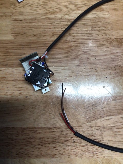
I never got clearified if medium really needs to be deenergized when using high so decided to wire up so it does. Needed four relays, one for each position ( 1, 2 and 3 ) and one ( a ) to deenergize relay 2 when selecting high. The relays is glued to a 1mm alunuminium sheet folded 90degrees.
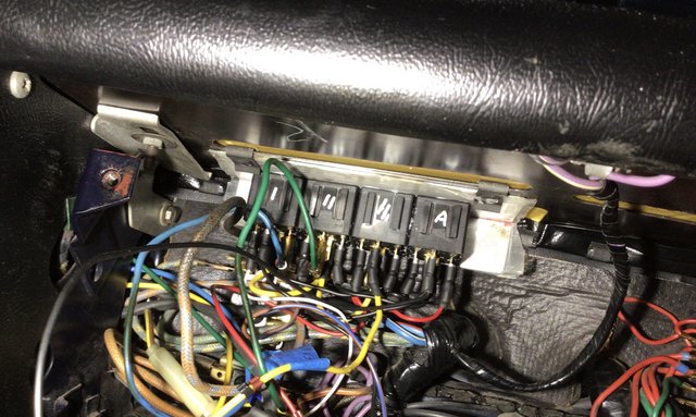
There is sheet metal in the «ceiling» above fuses with some slots, clipped the relay bridge into one of theese slots as deep and high as I could. It clears all other components in there. But since it is located just above open fuses/fuseholders I covered aluminium sheet with tape just in case it should fall down.
It works just fine.
Then I took a look at the original switch and there was a very neat indentention just were the spring blade rests at «low». Sanded it lightly with fine emery and filled it with polyester. ( The stuff boat people are using after they forgot to navigate ). This seems to be working fine, over time I don’t know, but this switch is going back next time I have to dig in there.
Harald

Here is what I did. I was able to use previous mentioned 4 position switch. Off / 1 / 1&2 / 1&2&3.
Drilled two holes in bracket, mounted it diagonally to get «off» position straight up, with original knob.
Pulled the brownblue ( energizing switch ), blue ( low fan ) and green ( medium fan ) wires out of the front case and routed them up behind the dash and into behind instrument panel. The brownblack wire continue down to the fan so I left it in place. But I spliced into it right before it enters front case with a wire and routed this the same way.
Now 4 thin wires ( one with power from brownblue with 3A fuse, and three for low, medium & high ) runs from the swithc behind front case and up behind instrument panel, were I also located the relays.
I never got clearified if medium really needs to be deenergized when using high so decided to wire up so it does. Needed four relays, one for each position ( 1, 2 and 3 ) and one ( a ) to deenergize relay 2 when selecting high. The relays is glued to a 1mm alunuminium sheet folded 90degrees.
There is sheet metal in the «ceiling» above fuses with some slots, clipped the relay bridge into one of theese slots as deep and high as I could. It clears all other components in there. But since it is located just above open fuses/fuseholders I covered aluminium sheet with tape just in case it should fall down.
It works just fine.
Then I took a look at the original switch and there was a very neat indentention just were the spring blade rests at «low». Sanded it lightly with fine emery and filled it with polyester. ( The stuff boat people are using after they forgot to navigate ). This seems to be working fine, over time I don’t know, but this switch is going back next time I have to dig in there.
Harald
| Link: | |
| BBcode: | |
| HTML: | |
| Hide post links |