Page 1 of 1
#1 oil pressure switch location
Posted: Fri Jan 28, 2022 1:30 am
by Brewer
The oil warning light on my 1972 OTS flickers, although the gauge reads 40-60 psi. I suspect I need to replace the switch but can't seem to locate it. The factory service manual suggests it's behind the washer tank and lower brake fluid reservoir but I can't see it - the only wire in the area goes to the brake slave cylinder. Another post on this forum says in 1972 the sensor & switch were moved up on top behind the throttle pedestal - nope, not there. Anyone have a suggestion?
#2 Re: oil pressure switch location
Posted: Fri Jan 28, 2022 6:55 am
by lowact
Two sensors, oil pressure gauge sender and oil pressure switch.
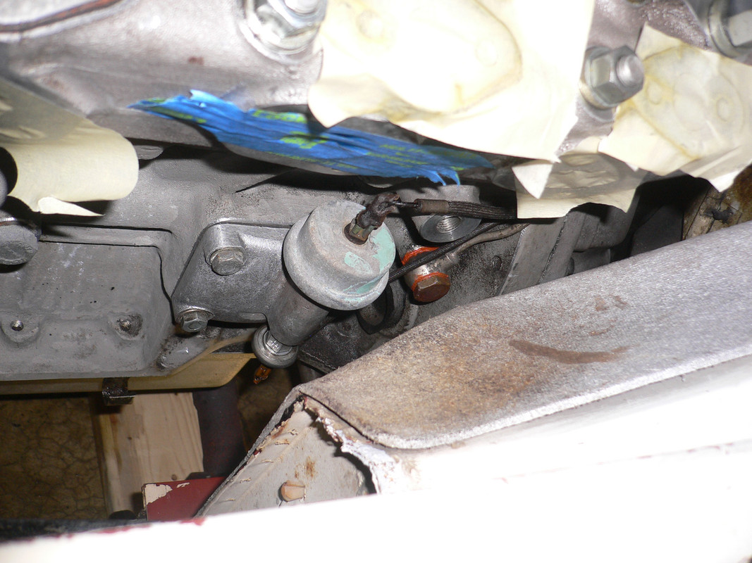
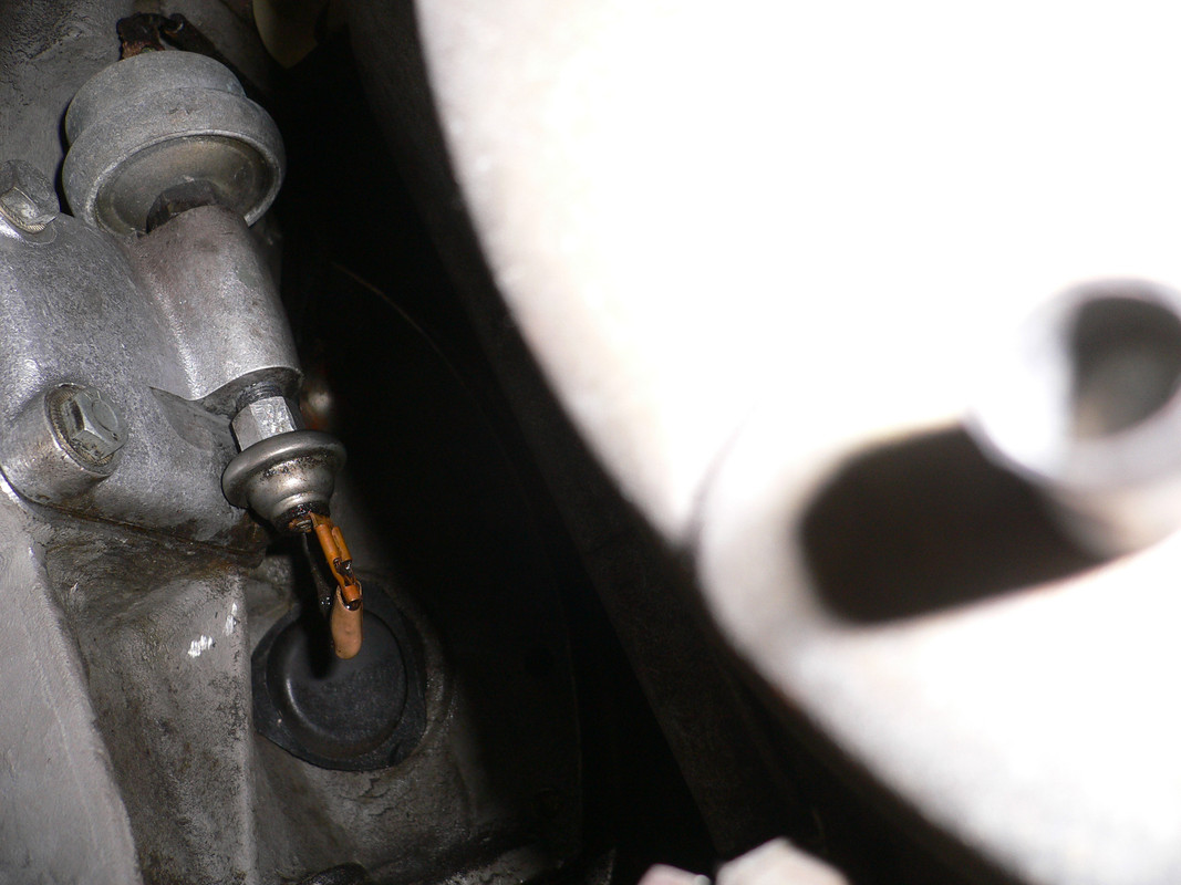
Early S3s had these on the back left hand side of the engine block up under the exhaust manifold, difficult to get to, you need to snake your arm in past the washer bottle and rear brake fluid reservoir ...
Later S3's moved them to the back of the valley, behind the throttle pedestal.
Wherever, the wires to these sensors run along the valley (from front right to back left) and over time get cooked, crack, this can cause the issues you describe.
Wire to the gauge sender is WN (white with brown tracer). wire to the oil warning light switch is BN (black with brown tracer). Follow these wires, you'll get to the sensors.
#3 Re: oil pressure switch location
Posted: Fri Jan 28, 2022 12:36 pm
by jfmassa
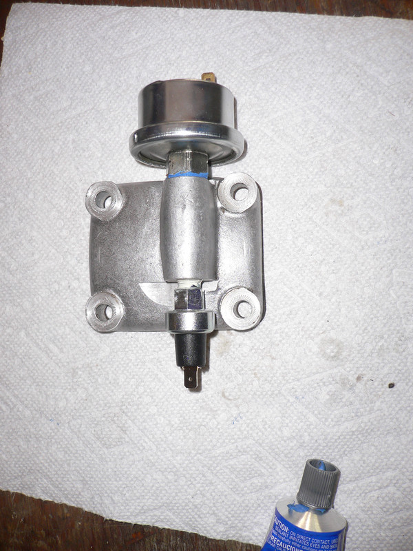
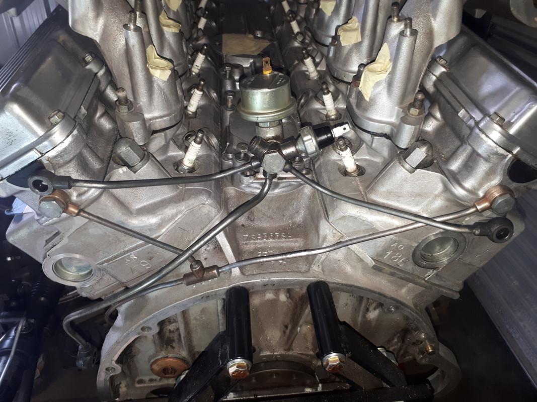
While replacing the exhaust manifold, I took the opportunity to replace the the oil pressure sender and switch (early 71). As noted in the prior post, the wiring takes a beating from the heat and oil. That harness is readily available and may be the source of the issue. These pictures show the unit.
regards,
Joe
#4 Re: oil pressure switch location
Posted: Fri Jan 28, 2022 12:38 pm
by jfmassa
While replacing the exhaust manifold, I took the opportunity to replace the the oil pressure sender and switch (early 71). As noted in the prior post, the wiring takes a beating from the heat and oil. That harness is readily available and may be the source of the issue. These pictures show the unit.
regards,
Joe
#5 Re: oil pressure switch location
Posted: Sat Jan 29, 2022 3:41 am
by lowact
Joe, what is the designation stamped on you old pressure gauge sender?
If it begins wih "PT" (I guess PT1811/10) and it still works, hang on to it, I expect you will find it preferable to the newer PTR type ...
#6 Re: oil pressure switch location
Posted: Sat Jan 29, 2022 4:58 am
by Brewer
Thanks, both of you, for the excellent direction. I've spotted it (using a borescope, I cheated). What a delightful location under the exhaust manifold! I can see why it was later moved to up on top. The wiring appears solid at this point.
#7 Re: oil pressure switch location
Posted: Sun Feb 20, 2022 1:45 am
by Brewer
Well, I replaced the warning light sensor today, probably the most difficult auto work I've done - and I've pulled engines & trannies before. Turns out there is an access panel below the brake booster - you'll need to remove the windshield washer bottle to get at the fasteners. Once off, you can snake your arm in above the brake line and just barely reach the sensor. Using a stubby 7/16 inch wrench, working one-handed and by touch, the job can be done. There is a sharp corner of a body panel perfectly placed to shred the back of your hand whilst working. Hurrah for the Coventry engineer who decided to move this to the top of the engine! Hopefully this solves my warning light issue.
#8 Re: oil pressure switch location
Posted: Sun Feb 20, 2022 2:39 pm
by lowact
Convert to RHD, then u can get in from the side

Still one handed and by touch ...
https://1drv.ms/v/s!AiSPBKa26IcchOYynzQfUveH291Alg
#9 Re: oil pressure switch location
Posted: Sun Feb 20, 2022 4:28 pm
by Brewer
Yes, but then I'd be on the wrong side to reach the drive-thru ATM. Gotta pay for all these parts somehow!

#10 Re: oil pressure switch location
Posted: Sun Feb 20, 2022 5:43 pm
by Craig Balzer
Brewer
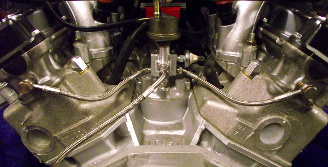
I'm not sure where you are but you can find the pieces on eBay (and other?) to piece together the newer oil feed system to get your sender off of the block and under the throttle pedestal.
Here's a start
https://www.ebay.com/itm/173866553163?h ... SwVtta6yO4
Alternatively, Rob Beere Racing has a very pretty $olution
http://www.rob-beere-racing.co.uk/pictures/DSCF2369.jpg
#11 Re: oil pressure switch location
Posted: Mon Feb 21, 2022 1:16 am
by lowact
That ebay one should be what Richard has, the cam shaft oil feed pipes when the oil gauge sender and switch are under the left hand exhaust manifold.
Here is comparison, the later type laid over the fitted original, the later type includes the mounting and connections for the sender and switch up at the back of the valley. Surplus to requirements if anyone is interested.
The RB one in yr 2nd photo is based on this but may be more suitable for early e-types, I interpret it mounts onto the valley cover by a single bolt?
Questions for anyone with an oem fitment of the later type:
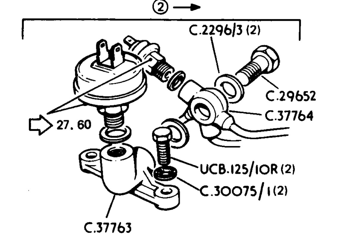
C3.7763 mounts via 2 screws however the e-type valley cover does not provide for these, I guess there is a simple adapter plate req'd? But not shown in any parts manual?
How were the previous sender and switch connections (under the manifold) closed off, screwed plugs into the same mounting plate or a whole new plate that was blank, without the connections? Again, not shown in any parts manual?
#12 Re: oil pressure switch location
Posted: Tue Feb 22, 2022 12:55 pm
by thermojac
Very interesting reading as I have a full scale deflection of my meter and I was wondering if there is a way of testing the sender unit before splashing out £80 to see if it cures my problem?
#13 Re: oil pressure switch location
Posted: Wed Feb 23, 2022 5:06 am
by lowact
1st thing to try, move the green wire that powers your oil pressure gauge from the battery (B) side of the instrument voltage regulator to the instrument (I) side of the voltage regulator. This will improve things because the newer (PTR) senders are voltage sensitive while the original (PT) senders were not. If happy enough with the result, do not read any further ...
viewtopic.php?f=6&t=13176
viewtopic.php?f=4&t=18515
PT senders have twin wire connector lugs in the center of the sender.
PTR senders have a single lug at the edge of the sender.
#14 Re: oil pressure switch location
Posted: Wed Feb 23, 2022 11:59 am
by thermojac
Thanks for your reply Colin. I had previously read the 13176 link you attached but I thought Julian had confirmed that the voltage regulator is not in the oil sender circuit?
#15 Re: oil pressure switch location
Posted: Wed Feb 23, 2022 2:05 pm
by lowact
Trying to stay on topic, added my reply onto that thread, cheers.
viewtopic.php?f=6&t=13176&p=150891#p150891
#16 Re: oil pressure switch location
Posted: Wed Feb 23, 2022 8:43 pm
by MarekH
Going slightly off away from the original topic, if you want to read a little bit further.... this is how it works.
There are three types of voltage in the car.
There are two types of sender in the car
Ammeter aside, there is one type of gauge.
The senders and gauges work together to split the voltage between them and this split is what is displayed on the gauge face.
The little gauges work on a bimetallic strip which is heated up and the needle deflects based on the heating effect of the current flowing through the bimetallic strip. How much current flows is dependent on the overall resistance of the gauge and sender together. The gauge has a resistance of about 60ohms.
A typical circuit like the fuel gauge circuit consists of a gauge and a resistive sender, whose values vary from ~20 ohms to 240 ohms. When the tank is empty, the sender resistance is high, not much current flows and the needle moves only about 60/(60+240) = 20% of the way across - i.e. only as far as far as "E". When the tank is full, the overall resistance is lower and the needle moves 60/(60+20) - about 75% of the across as far as "F". (I have used even numbers here - the fuel sender is about 25 to 245 ohms. Note also that the needle can go further in both directions than "E" or "F" - just connect a bigger or smaller resistance to verify that, e.g. disconnect the gauge and the resistance is infinite; short the sender and the resistance is zero...)
Voltage supplied can be one of three things. With the car running, full voltage is alternator voltage less any losses in the wiring. With the engine switched off, this will be battery voltage less any wiring losses. The third voltage is a lower regulated voltage of "10volts" from the dash regulator.
The original dash regulator is.... a bimetallic strip. It is set so that it heats up and cools down so it remains connected 5/6ths of the time. This means that if fed by 12volts, 10 volts pops out. If it is fed by a higher voltage, it heats up quicker and the 10/12 ratio becomes 10/13ths if fed by 13volts. The average voltage delivered is always 10volts. (You can check whether you have an original type dash regulator or a solid state type by connecting up a LED - it'll strobe if you have the old style regulator.)
The original oil sender works by a bimetallic strip mechanism. It is set to deliver a regulated voltage by default. In addition to this, the mechanism sits on a hinge with a cam which pushes the mechanism out. This changes the on:off ratio which is what makes the sender "work". This is why the old style oil sender works from "full voltage", not regulated voltage. This is the basis of why fitting a resistive only type of sender should be done from a regulated voltage, rather than full voltage.
Other than recalibrating how far the cam sits up (which was described recently), I would have thought that you ought to be able to make the gauge read higher by wiring two oil senders (old or new) in parallel to the gauge.
kind regards
Marek