Does anyone know what the pinion angle should be for the SIII IRS? Also, can anyone confirm at what angle the engine\gearbox sits when properly installed? Is it dead level or does it slope down toward the tail end of the gearbox?
Background:
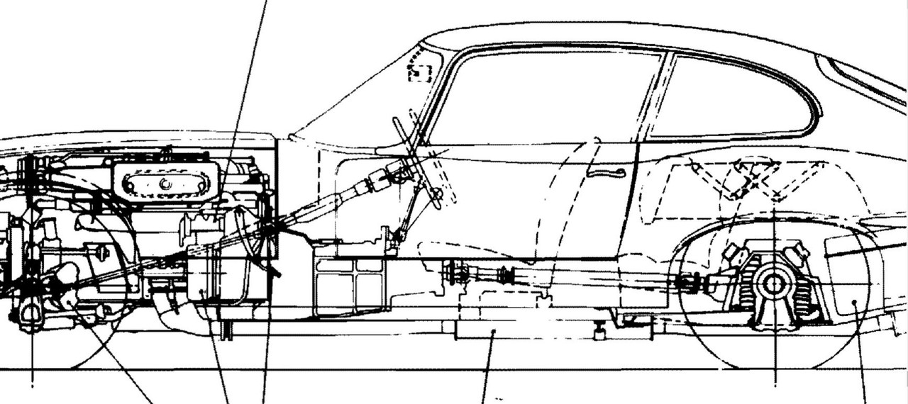
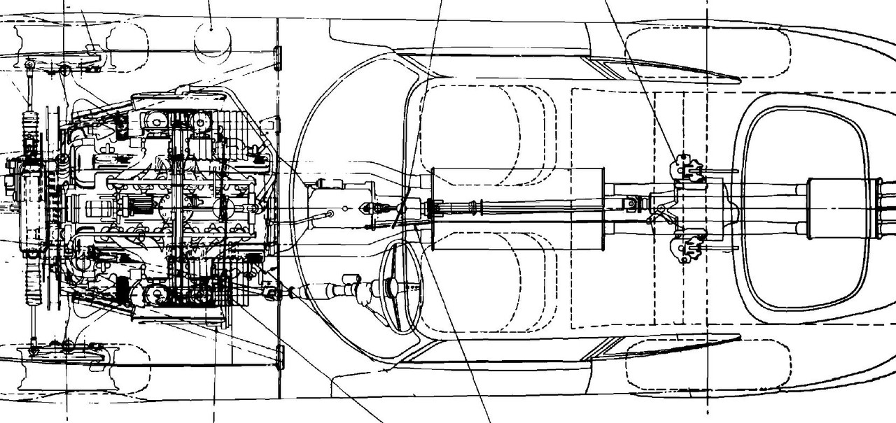
I have a JT5 installed as a conversion from automatic and get some vibration at high speeds(over 65). Tires are balanced, all U-joints are new on the balanced driveshaft and the axles. I noticed in the parts manual that the gearbox spacers for the rear trans mount are different between auto and manual(c-32458/2 vs c-7493). Anyone know the difference in thickness? Seeing as how I converted from auto to manual and only had my original spacers, could the difference in thickness of those spacers cause enough of a change in the driveline angle between the engine\gearbox and the differential pinion angle to be the source of the vibration? The trans mount on the JT5 is totally different that the original, no spring. The mount is similar to a chevy, being made of rubber, similar to the engine mounts except rectangular, not round. Also, the manual indicates spacers for the motor mounts showing "as required". "Required" to achieve exactly what? Engine height? Engine tilt side to side? Which one?
I know the two angles are supposed to be in parallel(e.g. engine 3* down - pinion 3* up) and that too much of a mismatch can cause a driveline vibration.
I have not been able to find this documented anywhere. If it is, could someone please point me to it?
I plan on doing some measurements in the future but would like to know what the angles SHOULD be as a starting point so that I can set everything right.
I know, lots of questions
Thanks,
Steve
SIII Driveline Angles
#2 Re: SIII Driveline Angles
Hi Steve,
I don't recall seeing any published figures for driveline angles but, if accurate, these two technical illustrations from the original S3 press release appear to show that in the static condition the design intent was that the gearbox output shaft should be horizontal with offsets which appear to be of the order of 3deg vertically and 3deg laterally to the diff pinion shaft.
Hope this helps,
Bob
Bob
'71 S3
'71 S3
Link: | |
BBcode: | |
HTML: | |
Hide post links |
#3 Re: SIII Driveline Angles
C7493 is superseded by C32458, they are the same?
For manual gearbox the mounting spring and the upper spring retaining plate are P/Ns C12299 and C34263.
For automatic transmission these are C19988 and C21932, to accommodate the heavier mass of the automatic.
Net result, the gearbox should "float" on the spring, i.e. it should find its own level. From its rest position you should be able to push it up or pull it down. If you can't do this, if the gearbox is hard up or hard down, if the spring is prevented from moving, that could very likely result in vibrations.
Note that the spring is damped, by the donut washer C29011 being an interference fit within the mounting bush C30159.
When I installed an overdrive unit I had to go the other way, due to the increased mass I had to swap out the manual spring and retaining plate for the automatic versions.
Regards,
ColinL
'72 OTS manual V12
ColinL
'72 OTS manual V12
Link: | |
BBcode: | |
HTML: | |
Hide post links |
#4 Re: SIII Driveline Angles
Thanks for the pictures Bob. It appears that the engine sits level but it looks like the differential pinion angle is up, but how much? Oh well, the measurements will tell.
lowact, as I stated in my original post, the JT5 uses a rubber mount instead of the stock trans mount. This is why I need to make sure that the trans tail is positioned vertically at the correct height to achieve an acceptable angle with regards to the pinion angle.
Thanks
lowact, as I stated in my original post, the JT5 uses a rubber mount instead of the stock trans mount. This is why I need to make sure that the trans tail is positioned vertically at the correct height to achieve an acceptable angle with regards to the pinion angle.
Thanks
Steve
1971 SIII E Type 2+2
Link: | |
BBcode: | |
HTML: | |
Hide post links |
#5 Re: SIII Driveline Angles
My experience with a JT5t in my 3.8 was that I overtightened the rear engine stabiliser and this caused a rattle.
Andrew.
881824, 1E21538. 889457. 1961 4.3l Mk2. 1975 XJS. 1962 MGB
http://www.projectetype.com/index.php/the-blog.html
Adelaide, Australia
881824, 1E21538. 889457. 1961 4.3l Mk2. 1975 XJS. 1962 MGB
http://www.projectetype.com/index.php/the-blog.html
Adelaide, Australia
Link: | |
BBcode: | |
HTML: | |
Hide post links |
#6 Re: SIII Driveline Angles
Might the vibration be due to other than tail-shaft alignment, e.g. why not half-shaft bearings?
To test the effect of tail-shaft alignment you could change it by packing out the mount with a lot of washers (easy without the spring) and test drive to see if this makes any difference, my money's on no.
Regards,
ColinL
'72 OTS manual V12
ColinL
'72 OTS manual V12
Link: | |
BBcode: | |
HTML: | |
Hide post links |
#7 Re: SIII Driveline Angles
Abowie: RE rear engine stabiliser, since this is a V12, there is no rear engine stabiliser. But the way the V12 twists under load when the motor mounts are hot & squishy, I have thought about maybe rigging something up along those lines. There ARE tapped bolt holes in the firewall and bellhousing. They might have originally had this in mind and then later decided it wasn't needed. And this is with the so-called uprated motor mounts.
lowact : All new bearings in the diff and the hubs. With the driveshaft disconnected it all rotates smooth as butter. CJ did a nice job for me on the IRS. Unless maybe, they didn't put back my original dog bones? Who knows?
Eventually I'll get around to measuring the angles, setting them to where they should be and see if it did any good. I was just hoping someone might have run across the design specs after all these years. Always a good starting point IMHO.
Thanks all!
Steve
1971 SIII E Type 2+2
Link: | |
BBcode: | |
HTML: | |
Hide post links |