


Hi,
I have a E-Type S3 V12 manual, just finishing a rebuild and desperately need a diagram of the small vacuum hoses that run from the thermo switch to the carbs, intake manifold, distributor etc. any help would be greatly appreciated.
Thank you
Vacuum system diagram


#2 Re: Vacuum system diagram
There are 5 versions of the thermostatic vacuum system illustrated in the spare parts manual. This copy is in the "E-type Knowledge Base" on this forum:
https://www.dropbox.com/s/xoy273abhzmg1 ... l.pdf?dl=1
https://www.dropbox.com/s/xoy273abhzmg1 ... l.pdf?dl=1
Regards,
ColinL
'72 OTS manual V12
ColinL
'72 OTS manual V12
| Link: | |
| BBcode: | |
| HTML: | |
| Hide post links |
-
Craig Balzer
- Posts: 90
- Joined: Fri Mar 03, 2017 2:02 am

#3 Re: Vacuum system diagram
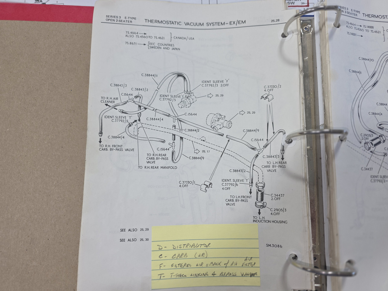
as colin stated, there are 5 versions of the plumbing for the thermostatic vacuum system.
This photo is of the version that is appropriate for my 72 S3 (UC 1S20954 with engine number 7S7765 SB). Note the post-it that IDs the letter identifiers on the thermostatic vacuum valve. I assume it to be the same of all variations of the thermostatic vacuum system.
Hope this helps
This photo is of the version that is appropriate for my 72 S3 (UC 1S20954 with engine number 7S7765 SB). Note the post-it that IDs the letter identifiers on the thermostatic vacuum valve. I assume it to be the same of all variations of the thermostatic vacuum system.
Hope this helps
Craig Balzer
Colorado Springs, CO, USA
1972 Series III OTS, 4-Speed (soon-to-be a Guy Broad 5-Speed), A/C, CWW
Colorado Springs, CO, USA
1972 Series III OTS, 4-Speed (soon-to-be a Guy Broad 5-Speed), A/C, CWW
| Link: | |
| BBcode: | |
| HTML: | |
| Hide post links |