Series1 4.2L Horn Testing & Repair

Technical advice Q&A

Topic author
JMW2310
Posts: 7
Joined: Fri Apr 20, 2018 10:53 pm
Great Britain

#1 Series1 4.2L Horn Testing & Repair

Post by JMW2310 » Sun Mar 01, 2020 7:19 pm

I am looking for some advice on the horns of my 1967 Series1 4.2l 2+2. They have never worked and I am looking to repair them, but first would like to establish whether the horns on the car are the correct ones (see photos).

Assuming they are original, I would like to get them working and before I check all the electrics I would like to send the horns off to be tested and if necessary repaired. Would anyone be able to advise:

1. Are they the correct horns for the car
2. Where can I get the horns tested and repaired?

Many thanks,


Image

Image

Image

Link:
BBcode:
HTML:
Hide post links
Show post links

User avatar

rswaffie
Posts: 1647
Joined: Sat Jul 19, 2014 7:56 am
Location: Lincolnshire
Great Britain

#2 Re: Series1 4.2L Horn Testing & Repair

Post by rswaffie » Sun Mar 01, 2020 7:55 pm

I have a 63 3.8, so I can’t confirm yours are correct as they probably different to mine. Are there any part no.s or make/model info? If so, compare these to the parts catalog and originality sections in the KB.
However, I did test and restore mine and I just hooked them up to a 12v supply to confirm that they worked.
Richard

Previous owner and restorer of a S1 3.8 FHC Opalescent Golden Sand with Tan Trim 889504 (now sold and headed for Athens)

:swerve: :wrench: :hammer: :fingerscrossed:

Link:
BBcode:
HTML:
Hide post links
Show post links


Topic author
JMW2310
Posts: 7
Joined: Fri Apr 20, 2018 10:53 pm
Great Britain

#3 Re: Series1 4.2L Horn Testing & Repair

Post by JMW2310 » Sun Mar 01, 2020 8:04 pm

Thanks for the advise. Is there a risk I could damage the horn on a 12v battery? Do I need to fuse the connection?

Link:
BBcode:
HTML:
Hide post links
Show post links

User avatar

rswaffie
Posts: 1647
Joined: Sat Jul 19, 2014 7:56 am
Location: Lincolnshire
Great Britain

#4 Re: Series1 4.2L Horn Testing & Repair

Post by rswaffie » Sun Mar 01, 2020 8:18 pm

To be honest, I don’t know. The electrical engineers on the forum will no doubt provide an answer! I worked on the basis that the two horns were driven via a relay so needed a decent amount of power to get them to work. From memory, I set my transformer to 12v but all I got was a ‘click’. I then used a 12v motorbike battery, fully charged, connected up the earth, and just touched the live side for a couple of seconds and they sounded as expected. Bloody loud when you are next to them!
Richard

Previous owner and restorer of a S1 3.8 FHC Opalescent Golden Sand with Tan Trim 889504 (now sold and headed for Athens)

:swerve: :wrench: :hammer: :fingerscrossed:

Link:
BBcode:
HTML:
Hide post links
Show post links

User avatar

mgcjag
Moderator
Posts: 8092
Joined: Fri Jul 09, 2010 6:15 pm
Location: Ludlow Shropshire
Great Britain

#5 Re: Series1 4.2L Horn Testing & Repair

Post by mgcjag » Sun Mar 01, 2020 8:30 pm

Is that really the correct horn...with "Made in Italy" stamped on it?....post number 33 here will help...Steve viewtopic.php?f=4&t=2007&start=20 here is a Lucas 9h
Image
Steve
69 S2 2+2 (just sold) ..Realm C type replica, 1960 xk150fhc

Link:
BBcode:
HTML:
Hide post links
Show post links


johnetype
Posts: 474
Joined: Sun Feb 26, 2012 11:54 pm
Location: Worcestershire
Great Britain

#6 Re: Series1 4.2L Horn Testing & Repair

Post by johnetype » Mon Mar 02, 2020 12:17 am

JMW2310 wrote:
Sun Mar 01, 2020 8:04 pm
Thanks for the advise. Is there a risk I could damage the horn on a 12v battery? Do I need to fuse the connection?
No, they are designed for 12 volts. No need for a fuse if you're just connecting them momentarily to a battery to test them but use substantial wire as they draw a reasonable current similar to the headlight bulbs.
John

1969 Series 2 FHC

Link:
BBcode:
HTML:
Hide post links
Show post links


Topic author
JMW2310
Posts: 7
Joined: Fri Apr 20, 2018 10:53 pm
Great Britain

#7 Re: Series1 4.2L Horn Testing & Repair

Post by JMW2310 » Sat Mar 14, 2020 8:09 am

Many thanks John, much appreciated.

Link:
BBcode:
HTML:
Hide post links
Show post links


christopher storey
Posts: 5698
Joined: Sun Mar 09, 2008 3:07 pm
Location: cheshire , england
Great Britain

#8 Re: Series1 4.2L Horn Testing & Repair

Post by christopher storey » Sat Mar 14, 2020 9:55 am

mgcjag wrote:
Sun Mar 01, 2020 8:30 pm
Is that really the correct horn...with "Made in Italy" stamped on it?
I would lay heavy odds that the Italian horn is not original. All E horns were Lucas and I do not believe any were outsourced from Italy

Link:
BBcode:
HTML:
Hide post links
Show post links

User avatar

Heuer
Administrator
Posts: 14766
Joined: Sat Mar 01, 2008 5:29 pm
Location: Nottinghamshire
Great Britain

#9 Re: Series1 4.2L Horn Testing & Repair

Post by Heuer » Sat Mar 14, 2020 11:42 am

:yeahthat:
David Jones
S1 OTS OSB; S1 FHC ODB
1997 Porsche 911 Guards Red

Add your E-Type to our World Map: http://forum.etypeuk.com/viewtopic.php?f=1&t=1810

Link:
BBcode:
HTML:
Hide post links
Show post links


MarekH
Posts: 1567
Joined: Wed Jul 21, 2010 8:30 pm
Location: Surrey
Great Britain

#10 Re: Series1 4.2L Horn Testing & Repair

Post by MarekH » Sat Mar 14, 2020 1:16 pm

johnetype wrote:
Mon Mar 02, 2020 12:17 am
......... but use substantial wire as they draw a reasonable current similar to the headlight bulbs.
No - they draw substantially more than headlights.

A 60W bulb will draw 5amps if designed to be powered by 12volts.
The horns are about 1.5ohms, so will draw almost 10 amps, powered by 12v.

There are going to be two in parallel when fitted, so that circuit will draw ~20amps.
That's why the horns got a horn relay but the headlights got nothing.

kind regards
Marek

Link:
BBcode:
HTML:
Hide post links
Show post links


johnetype
Posts: 474
Joined: Sun Feb 26, 2012 11:54 pm
Location: Worcestershire
Great Britain

#11 Re: Series1 4.2L Horn Testing & Repair

Post by johnetype » Sat Mar 14, 2020 8:10 pm

MarekH wrote:
Sat Mar 14, 2020 1:16 pm
johnetype wrote:
Mon Mar 02, 2020 12:17 am
......... but use substantial wire as they draw a reasonable current similar to the headlight bulbs.
No - they draw substantially more than headlights.

A 60W bulb will draw 5amps if designed to be powered by 12volts.
The horns are about 1.5ohms, so will draw almost 10 amps, powered by 12v.

There are going to be two in parallel when fitted, so that circuit will draw ~20amps.
That's why the horns got a horn relay but the headlights got nothing.

kind regards
Marek
Marek,

If you'd tested it, as I did, you'll find that each horn draws a little over 2 amps so headlight gauge wire is perfectly suitable for the purposes of the original poster which is to connect a horn to a 12 volt battery momentarily to check it works. If fact you need both horns in parallel to get close to your 5 amps for a headlight.

The reason for the horns having a relay when on the car is that the horn contact in the steering wheel can't handle the surge current when the horns are connected or the back emf when disconnected reliably. The wiring can handle the 4.5 amps comfortably.
John

1969 Series 2 FHC

Link:
BBcode:
HTML:
Hide post links
Show post links

User avatar

Robsan
Posts: 129
Joined: Wed Jan 20, 2016 1:48 pm
Location: Cleveland UK
Great Britain

#12 Re: Series1 4.2L Horn Testing & Repair

Post by Robsan » Sat Mar 14, 2020 9:12 pm

did someone say 1.5 Ohms

V = I x R

or I = V/ R

if V = 12V

R = 1.5 Ohm

THen I = 12/ 1.5= ??

The I [Amperage] is governed by the Resistance R in DC systems

hope this helps

rob

Link:
BBcode:
HTML:
Hide post links
Show post links


MarekH
Posts: 1567
Joined: Wed Jul 21, 2010 8:30 pm
Location: Surrey
Great Britain

#13 Re: Series1 4.2L Horn Testing & Repair

Post by MarekH » Sat Mar 14, 2020 10:32 pm

I'd measure the resistance of this horn. If it draws a steady ~2amps, then at ~12v it ought to have a resistance of ~6ohms. My guess is that it is much much lower than that and so the only [EDIT]-insert way I reconcile your mentioning of surge current and back emf.

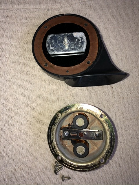
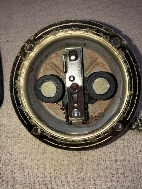
The way the horn works is basically an electromagnet attached to a diaphragm and it has a set of contacts which are open/closed depending on how far the thing moves. To produce a tone of say, 500Hz, the electromagnet and diaphragm move back and forth 500 times per second. That means the solenoid plunger moves in and out 500 times per second, making and breaking the circuit 500 times per second for all of the time that the horn button remains pressed.

Your horn probably has a coil resistance of about 1.5ohms - it is close to a short circuit and will easily pull 10 amps when connected. This drops rapidly down to a much lower number. That number is zero when it is disconnected, which it is 500 times per second. Your measured current is just an averaged out reading because the meter cannot respond fast enough to the changing current. You'll need an oscilloscope to see it changing 500 times a second.

The problem (like the solenoid which engages an overdrive) is that if the horn contacts decide to corrode and weld themselves shut, it doesn't oscillate at 500Hz, make a loud noise and consume the average current you measured, but it simply remains connected, pulling that high current 100% of the time. The relay contacts and steering wheel horn contacts are actually quite robust, but not having a relay would mean that the failure mode would be that rather than an average current you've measured going through a relay, you would now have the full startup (and never dropping) surge current coming through the ignition switch and all of the common wiring. Smoke will escape.

The relay also means this continuously changing high to low current (when it is working ok) stays out of the same circuit common with the ignition, as it is powered directly by a brown wire. This means your flyback voltage spikes, caused by the connection and disconnection of an inductive load) don't interfere with the ignition. (Neither the horn push contact, nor the horn relay are the contacts which are opening and closing at 500 times per second - that goes on at the contact breaker in the horn itself.)

I mentioned the overdrive solenoid because it is basically the same thing, but without a rubber diaphragm and contact breakers attached to make it make a loud noise. It pulls 16amps to engage the overdrive (your "surge current") and 0.9amps to remain engaged (your "my meter measures" amount). These are published figures, not mine. I've watched what happens when one of these solenoids fail under test and smoke literally does start escaping straight away. I hit the "off" button pretty damned fast.

The wiring is indeed happy to take a constant 4 amps, but what is actually happening is that it is seeing a rapidly pulsing high current which merely averages to that if you keep the horn pressed. A quick toot on the horn really will pull 20 amps or more. It is not a simple DC load and a meter does not measure it right.

kind regards
Marek

Link:
BBcode:
HTML:
Hide post links
Show post links


johnetype
Posts: 474
Joined: Sun Feb 26, 2012 11:54 pm
Location: Worcestershire
Great Britain

#14 Re: Series1 4.2L Horn Testing & Repair

Post by johnetype » Sun Mar 15, 2020 9:30 am

Marek,

You've said some things above that are correct and some that are wrong but fundamentally you need to understand the difference between resistance and impedance.

The overdrive solenoid does follow some of the same principles as the horn but it's a poor comparison here as the overdrive solenoid has been deliberately constructed to have a large pull in force - and hence current - and a lower holding force and current so it can be left engaged for hours without burning out.

The DC meter does read "right". It measures the average current which is the one the wiring cares about and is the one relevant to the original post about connecting a horn up to a battery to test with the appropriate wire size.
John

1969 Series 2 FHC

Link:
BBcode:
HTML:
Hide post links
Show post links


christopher storey
Posts: 5698
Joined: Sun Mar 09, 2008 3:07 pm
Location: cheshire , england
Great Britain

#15 Re: Series1 4.2L Horn Testing & Repair

Post by christopher storey » Sun Mar 15, 2020 12:06 pm

John : I'm sorry, but I think your suggestion that each horn draws 2 amps is entirely ( and dangerously ) wrong. Generally speaking , horns need at least 10 amps draw-in current, and since, unlike an OD solenoid , the diaphragm is not continuously held in, the current is required each time the diaphragm is drawn in i.e something like 440 times a second dependent upon pitch. This is as near to continuous current as it can be, and the suggestion that it is ok to use thin wire is a recipe for a fire if e.g. a horn should stick on

Link:
BBcode:
HTML:
Hide post links
Show post links


MarekH
Posts: 1567
Joined: Wed Jul 21, 2010 8:30 pm
Location: Surrey
Great Britain

#16 Re: Series1 4.2L Horn Testing & Repair

Post by MarekH » Sun Mar 15, 2020 3:22 pm

Dear John,
I think I might just understand the difference - I'll stand by what I've said. In fact I'd go further and say that the difference between resistance and impedance has nothing to do with this.

1/ Resistance is to impedance what DC is to AC

2/ An inductor is the opposite of a capacitor.

3. Inductors act to keep current flow constant. That's why you see a phenomenal back EMF when you turn off. I think that might be Lenz in about 1880 or so who saw this first so it will have been in your school physics textbook.

4/ Impedance versus resistance isn't your answer here. This isn't a nice AC sine wave you are dealing with. You need to impress me with inductance:- that graph of current versus time basically starts with current=infinity on the left which it drops like a stone and then levels out. All inductors follow this graph. The overdrive solenoid gets to the right hand side of the graph and the level, steady current draw (at which point, a simple meter knows what to do). The horn graph starts exactly the same:-just as high, then it drops just as fast BUT the graph gets chopped off in its prime after 1/500th of a second and it then repeats like Groundhog day starting from the right hand side high current bit and dropping fast again and then restarting again and again and again. We're just get lucky with the overdrive as it turns on once and stays turned on - that's the ONLY difference between the two here.

6/ You implied that the steering column push button couldn't cope with the back EMF, but it is contacts in the horn which are making and breaking contact, so the "points wear" and electrical noise generation is happening 500 times as much in the horn itself as in the horn push.

Your "meter" is about as useful for this analysis as a steam roller is as a formula one pace car. The meter shows you a boring slow steady average*, but behind the headline number is a lot of rapid noisy very high speed stop start action. If you want to see what you think is a simple impedance, I can lend you my Tektronix oscilloscope, because you won't see it on a meter, no matter what setting you're using.

And tell me specifically which bit I've said is wrong so I can correct it. I'd hate to think I've misled anyone or given bad advice.

kind regards
Marek

*apologies to the late Fred Dibnah.

Link:
BBcode:
HTML:
Hide post links
Show post links


MarekH
Posts: 1567
Joined: Wed Jul 21, 2010 8:30 pm
Location: Surrey
Great Britain

#17 Re: Series1 4.2L Horn Testing & Repair

Post by MarekH » Sun Mar 15, 2020 3:42 pm

Alternatively,
1/ Yes you can test your horns by tapping a wire to the battery momentarily. (Prepare to be deafened.)
2/ John's meter probably doesn't even read reliably when set to amps but he doesn't know this yet. Most little meters don't. It most certainly doesn't read "right" as he thinks because it'll be trying to measure an AC sine wave through a bridge rectifier, not a complicated type of saw tooth waveform of an inductive load.
3/ If you don't want to know how it works, ignore most of the stuff in between. Just go back to the Dibnah channel on Dave.

kind regards
Marek

Link:
BBcode:
HTML:
Hide post links
Show post links


Frantic
Posts: 5
Joined: Tue Jun 02, 2020 3:24 pm
Location: Gees, Netherlands
Netherlands

#18 Re: Series1 4.2L Horn Testing & Repair

Post by Frantic » Mon Apr 05, 2021 8:42 am

Perhaps a bit late to the party, but my '67 Series 1 4.2L Open Headlights has the same Italian plastic horns, only with a red body.
The brand is Stebel, model TM80.
A bit of research shows that this is a fairly big manufactorer still today.
It does seem like OE, which is hinted by the extra single hole bracket on the existing two hole horn bracket to accommodate the single bolt attachement from this horn. The single hole bracket looks not to have been added later on the car, but of course could have been there for an earlier (different) horn with one bolt.

This Stebel is a fairly modern looking unit and I wasn't yet able to find out since when they started production.

Maybe this helps.
Best
Frans
PS a simple test with a 12V charger will show if they work, mine do
Last edited by Frantic on Mon Apr 05, 2021 8:56 am, edited 1 time in total.
Frans
'67 Series 1 OTS Open Headlights
'70 Triumph Spitfire Mk3
2007 Jaguar XK

Link:
BBcode:
HTML:
Hide post links
Show post links

User avatar

mgcjag
Moderator
Posts: 8092
Joined: Fri Jul 09, 2010 6:15 pm
Location: Ludlow Shropshire
Great Britain

#19 Re: Series1 4.2L Horn Testing & Repair

Post by mgcjag » Mon Apr 05, 2021 8:55 am

Hi Frans...Red Italian plastic horns were not OE on an E type. ...Steve
Steve
69 S2 2+2 (just sold) ..Realm C type replica, 1960 xk150fhc

Link:
BBcode:
HTML:
Hide post links
Show post links


Frantic
Posts: 5
Joined: Tue Jun 02, 2020 3:24 pm
Location: Gees, Netherlands
Netherlands

#20 Re: Series1 4.2L Horn Testing & Repair

Post by Frantic » Mon Apr 05, 2021 9:03 am

Hi Steve,
Good to know. I will start looking for a single of double bolt pair of originals ;-)
Best
Frans
PS I read your post on the Lucas horns. Do you happen to know which horn model was fitted to the later 4.2L cars with the brackets on the picture frame? My car is 1e-154xx.
PS2 Maybe this one? Lucas 9H windtone horn with two terminals. Jaguar XK120, XK140 and XK150 (1948-61) • E-Type Series 1 and 2 (1961-70) - OK I believe that this was what you were suggesting! Sorry.
Frans
'67 Series 1 OTS Open Headlights
'70 Triumph Spitfire Mk3
2007 Jaguar XK

Link:
BBcode:
HTML:
Hide post links
Show post links

Post Reply Previous topicNext topic