Tacho Not Working

Talk about the E-Type Series 3
User avatar

lowact
Posts: 625
Joined: Mon Oct 09, 2017 10:05 am
Location: Canberra, Australia
Contact:
Australia

#21 Re: Tacho Not Working

Post by lowact » Sun May 01, 2022 11:51 am

Ian, fyi:
The plug with the loop in it is represented on the wiring diagram by three plug symbols, one symbol for each of the circuits that share this plug, i.e.:
Image

A 4-pin plug with loop is used instead of a 3-pin plug for convenience of removing the tacho, i.e. so that on one side of the plug there is only the tacho.

Cutting/removing the loop is the same as opening the connector in the W wire “run input to ballast”.

There are two WU wires, not to be mixed up. The one with the linear (straight) tracer is the “cranking input to ballast”. The one with the non-linear (spiral or ring) tracer is the tacho sensor wire.

Your renewed tacho should work perfectly when wired up exactly as per the oem arrangement, including sensor wire from the front of the ballast resistor instead of the –ve coil terminal. If it doesn’t (?) simply swap the sensor wire from the ballast resistor to the –ve terminal of the coil, either way will not damage anything.
Regards,
ColinL
'72 OTS manual V12

Link:
BBcode:
HTML:
Hide post links
Show post links

User avatar

Topic author
IFC123
Posts: 23
Joined: Thu May 05, 2016 7:31 pm
Location: Doncaster
Great Britain

#22 Re: Tacho Not Working

Post by IFC123 » Sun May 01, 2022 3:56 pm

Hi Colin,
Thanks for your reply.
Just to summarise, in my case i had a green wire and 3 braided wires going into the plug.
I cut the green wire & attached that to the new green wire from the tacho.
I checked continuity of the other 3 braided wires and found the one that went to the ballast resistor and then connected that to the blue & white wire from the tacho, also moving the other end from ballast resistor to neg side of the coil.
I now have 2 braided wires (one with a small black plastic tube/ring) with female ends that connected to the loop in the original tacho wiring.
So from reading Marek's posts I am assuming all I need to do is either join these 2 wires or make a new loop to connect these?
That is assuming they are still connected where they were originally.

regards
Ian
Ian
1971 e type V12 LHD, 1991 Merc SL 300, 2001 DB7

Link:
BBcode:
HTML:
Hide post links
Show post links


MarekH
Posts: 1567
Joined: Wed Jul 21, 2010 8:30 pm
Location: Surrey
Great Britain

#23 Re: Tacho Not Working

Post by MarekH » Sun May 01, 2022 9:20 pm

It'd probably be best to refer to wire colours rather than "braided wires".

Your mission is to identify the white wire coming from the ignition switch and the white wire coming from the ballast resistor and make sure they are connected.

kind regards
Marek

Link:
BBcode:
HTML:
Hide post links
Show post links

User avatar

lowact
Posts: 625
Joined: Mon Oct 09, 2017 10:05 am
Location: Canberra, Australia
Contact:
Australia

#24 Re: Tacho Not Working

Post by lowact » Mon May 02, 2022 2:44 am

On the plug, the two wires that need to be connected to the tacho are diagonally opposite, i.e. the G power wire and the WU sensor wire are diagonally opposite. I expect that the sensor wire is the one with the "small black plastic tube/ring", I expect that the ring colour is blue, not black?
Image

The other two (opposite diagonal) unmarked white wires need to be connected, to connect from the ign switch to the correct (!) terminal on the ballast resistor.
Regards,
ColinL
'72 OTS manual V12

Link:
BBcode:
HTML:
Hide post links
Show post links

User avatar

Topic author
IFC123
Posts: 23
Joined: Thu May 05, 2016 7:31 pm
Location: Doncaster
Great Britain

#25 Re: Tacho Not Working

Post by IFC123 » Tue May 03, 2022 7:57 pm

Hi Marek/Colin,
Thanks for your help with this.
I thought I would post some pictures of the ballast resistor connections on my car, they certainly seem to be at odds with the wiring diagram.
The blue & white wire attached is not one of the 3 wires coming from the tacho connection, so I assume it is the one going to the ballast relay.
The white wire going to the negative side of the coil is from the tacho connection.
The other white wire, joined by a PO to the black wire is connected to the other side of the ballast resistor, is from the tacho connection, but not sure why its on that side.
Not sure why there are only 2 wires at each side of the BR, but there are only 2 spade connectors on the near side.
There seem to be 2 wires, blue/white & black/red to the Amp missing.
I will trace all the wires back to ignition etc when I get back from holiday.

Image

Image

Image
Ian
1971 e type V12 LHD, 1991 Merc SL 300, 2001 DB7

Link:
BBcode:
HTML:
Hide post links
Show post links


MarekH
Posts: 1567
Joined: Wed Jul 21, 2010 8:30 pm
Location: Surrey
Great Britain

#26 Re: Tacho Not Working

Post by MarekH » Tue May 03, 2022 8:38 pm

It's thirteen months since you started this thread and you now disclose that your car is not wired as per the Jaguar wiring diagram. To date, the advice given has assumed your car was standard. I don't think any of us can help you until you make a wiring diagram of what is connected to what. It is foolish to assume anything at all given this new information.

Failing that, disconnect your tacho and put the car back into a state where it starts and runs normally and you can then think about the tacho later, when you know what works, what doesn't, what colour wires are connected to what and what is different to standard.

kind regards
Marek

Link:
BBcode:
HTML:
Hide post links
Show post links

User avatar

Topic author
IFC123
Posts: 23
Joined: Thu May 05, 2016 7:31 pm
Location: Doncaster
Great Britain

#27 Re: Tacho Not Working

Post by IFC123 » Tue May 03, 2022 8:58 pm

Marek,
As I stated in my 1st post, electrics is not a strong point.
Until I started checking the wires and became more familiar with the wiring diagram, following the advice on here I didn't know it wasn't standard.
I apologise for wasting your time
Ian
1971 e type V12 LHD, 1991 Merc SL 300, 2001 DB7

Link:
BBcode:
HTML:
Hide post links
Show post links


MarekH
Posts: 1567
Joined: Wed Jul 21, 2010 8:30 pm
Location: Surrey
Great Britain

#28 Re: Tacho Not Working

Post by MarekH » Wed May 04, 2022 6:07 am

Post your version of the diagram like Colin did from the manual. You're going to need that anyway as your ballast appears to be non-standard, so perhaps the rest of the ignition is also non-standard.

Your car started, so we know it didn't have a fuel problem.

It also means the ignition system works when fed by the white/yellow wire from the spring loaded position3 on the ignition switch.

You know it doesn't work when fed by its normal white wire feed from position2. You know you need to trace that white wire continuity as it hops from behind the dash, to the ballast and then through the ballast (if that is what it does) and then onwards. You also know one good reason why that white feed was broken.

The s3 was originally offered as both a 6cylinder car and as a 12cylinder car. The 6cylinder car had a tacho which worked just like an inductive timing light worked. The ignition pulses were sensed by the tacho by sampling the change in magnetism on the white wire on the way to the coil. The v12 OPUS ignition system did it differently. The wiring loom thus accommodated more than one option. Added to that, the v12 moved the ballast and coil from the front left hand cam cover to the back during the production run, so there are legacy items in the loom - not all wires "make sense".

A ballast usually performs two functions:-
1/ It is harder to start a car than to keep it running and starting a car drains the battery. During cranking, the coil is usually fed either directly or via only a small resistance, so it gets full voltage to start. During normal running, it is fed through an additional resistance so it is not overfed.
2/ The clue is in the title for this one. The material chosen for the resistance in the ballast is chosen very carefully because its resistance properties vary with temperature. The temperature of the ballast resistor depends on the coil charging current running through it. At high rpm, the coil has little time to charge up so receives less cumulative current inflow. It cools down a bit. This makes the ballast resistor resistance drop a bit. More current flows in quicker to recharge the coil at high rpm so you get a good spark at high rpm. At idle, the opposite happens. The coil has too much time to recharge and so is fed too much current. The ballast resistor resistance goes up and so it limits the current going to the coil, thus stopping it from overheating. Some ballasted ignition systems simply used a specially chosen wire made of the right material as the resistor, so don't assume anything about cutting and replacing wires until you have documented what you actually have fitted.

Worry about the tacho later once your car is up and running normally.

kind regards
Marek

Link:
BBcode:
HTML:
Hide post links
Show post links

User avatar

lowact
Posts: 625
Joined: Mon Oct 09, 2017 10:05 am
Location: Canberra, Australia
Contact:
Australia

#29 Re: Tacho Not Working

Post by lowact » Wed May 04, 2022 1:17 pm

Yes, photos better than words but diag more complete.
Can yr diag be of how it was before your mods?

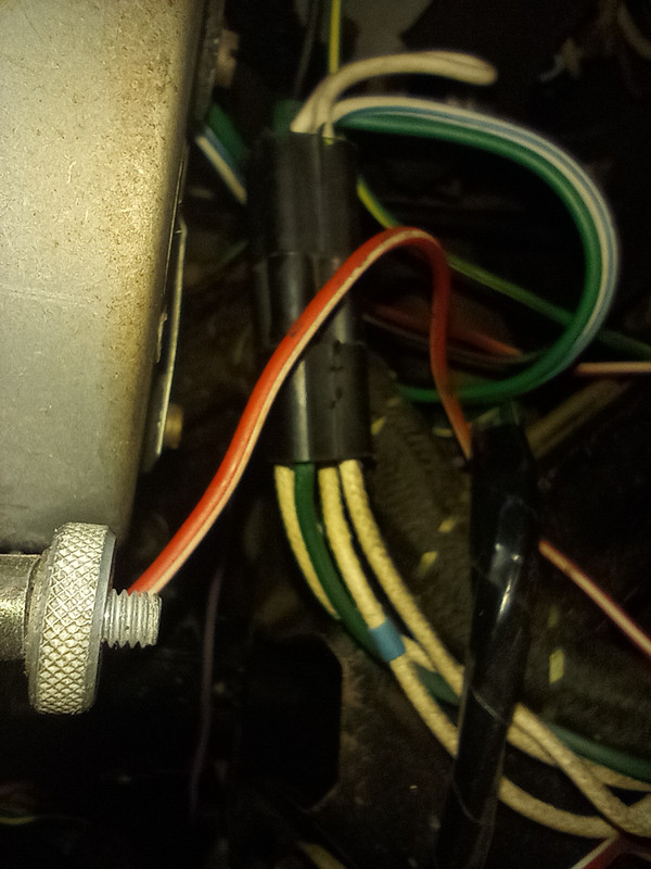
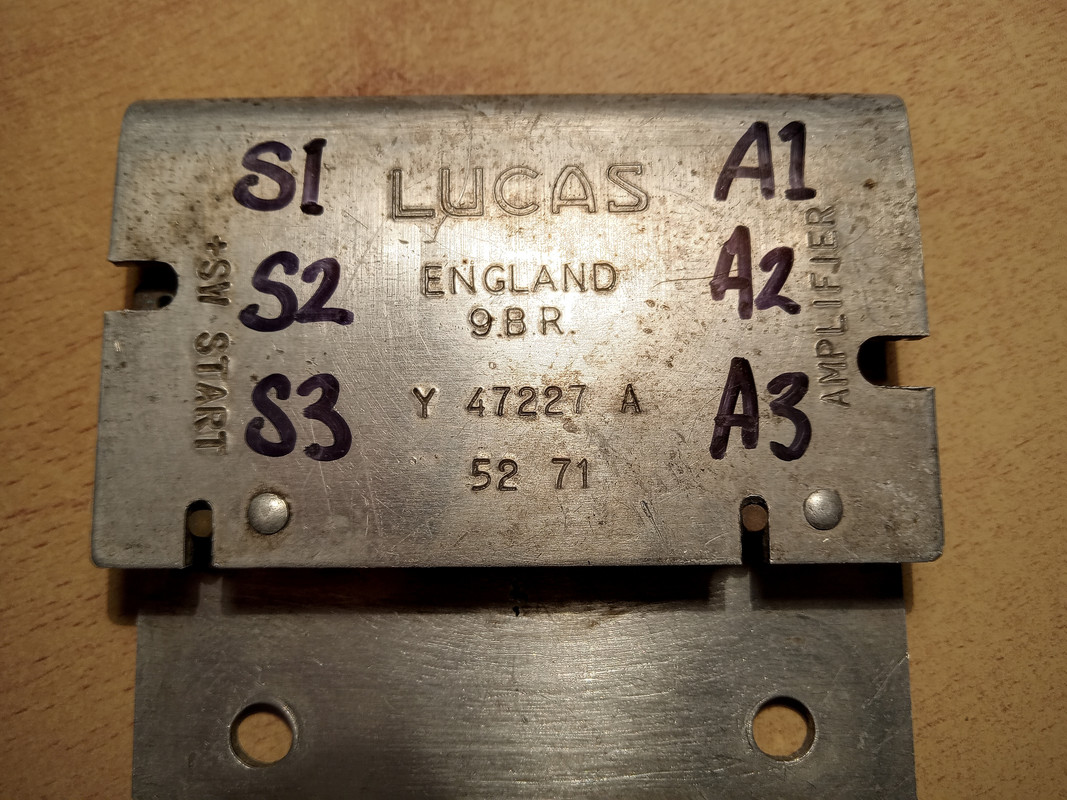
There were 2 versions of the ballast resistor, before and from engine number 7S7560. My car should have had the early version but had the later, i guess because the earlier became NLA. Below is a pic of my ballast, is yours the same? It was mounted to the front of the A-bank cam cover, same as yours is.
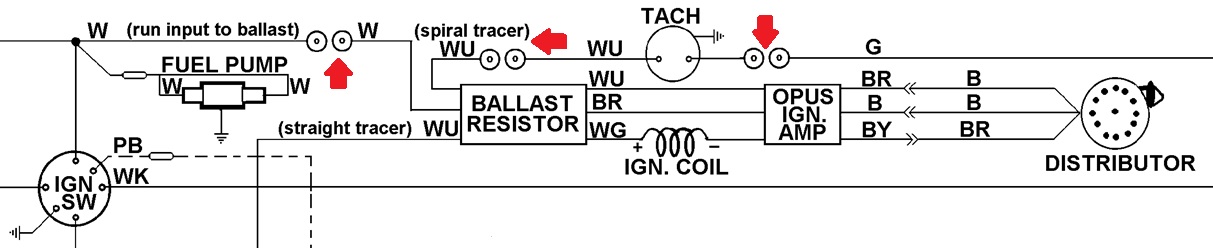
If so, can we use the following names for the ballast resistor terminals?
S = "start sw" side, A = "amplifier" side.
Image

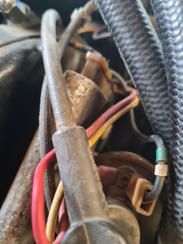
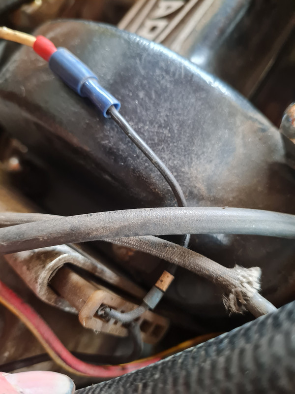
The temperature dependent ballast resistor gets relatively hot. Over time, the S-side wire terminations become brittle and fail, need to be re-terminated. Easiest way to do this is to cut off the common side plug and fit individual spade connectors. Looks like what your PO had done, I also had to do this.

To check yr ballast, disconnect all wires and, using your multimeter, check for continuity from S1 to A3. If there is any non-continuity, yr ballast is stuffed, you need to buy/fit a new one. Or you can have mine.
If there is no continuity probably why your tacho didn’t work.

My opinion on why tacho’s sense from the Opus ballast resistor instead of from the coil -ve, keen to hear from others re this:

The role of the ballast resistor is to ensure that the coil and also the ignition electronics get all the available energy when the engine is cranking and is not overloaded at other times, is why there are 2 inputs, the “run” input from the ign switch (W wire) and the “cranking” input from the start relay (next to the wiper motor, WU straight trace wire). The tacho counts the frequency of the pulses induced by the coil firing. These pulses can be detected in any connected wiring, not just at the coil -ve. The Opus ballast resistor has built-in compensation (via additional resistance) to provide for a tacho signal that has a relatively consistent “amplitude”, irrespective of whether it is starting or cranking voltage that is being applied to the coil, more reliably counted by legacy tachos; this consistency is lost if the tacho sensors directly from the –ve side of the coil. Not that you would notice, with new TI electronics.

Imo an important take from these explanations. You can wire the ballast resistor incorrectly and not realise it. You could even remove it. The car (and tacho) could still run seemingly perfectly well. However cold starting could become an issue and or the coil or amplifier would fail prematurely. I.e just getting it to run is not the solution, getting it to oem, that’s the solution.
Image
Regards,
ColinL
'72 OTS manual V12

Link:
BBcode:
HTML:
Hide post links
Show post links

User avatar

Topic author
IFC123
Posts: 23
Joined: Thu May 05, 2016 7:31 pm
Location: Doncaster
Great Britain

#30 Re: Tacho Not Working

Post by IFC123 » Wed May 04, 2022 8:17 pm

As soon as I get back I'll do a wiring diagram (pre changes) some continuity checks and post some more photos.

regards
Ian
Ian
1971 e type V12 LHD, 1991 Merc SL 300, 2001 DB7

Link:
BBcode:
HTML:
Hide post links
Show post links

Post Reply Previous topicNext topic