


For those that don't want to wade through this rather turgid stuff, and cut to the chase, here are the facts, drawn together after the various exchanges and study of parts that various Forum members were kind enough to supply or measure themselves. If you don't agree with these, please read and understand the Physics and the Arithmetics before you comment.
The 3.8 Front and Rear brake master-cylinders are not the same, but they have the same 5/8" bore ; the differences are down to the piston travel available which should be 1" for the Rear (top) and 1-3/8" for the Front (lower). This longer front travel is to take account of bigger front-pad push-back and bigger front-caliper pistons. Under normal operating circumstances this difference is irrelevant and using the "wrong" cylinders (ie two 'shorts') makes no difference whatsoever to braking split or power.
In extreme circumstances (slack front wheel-bearings ?) it just means you'll have to pump one more time to get the fronts hardened up. Essentially, the components within each (identical) cylinder form a combined length of about 101-102mm.
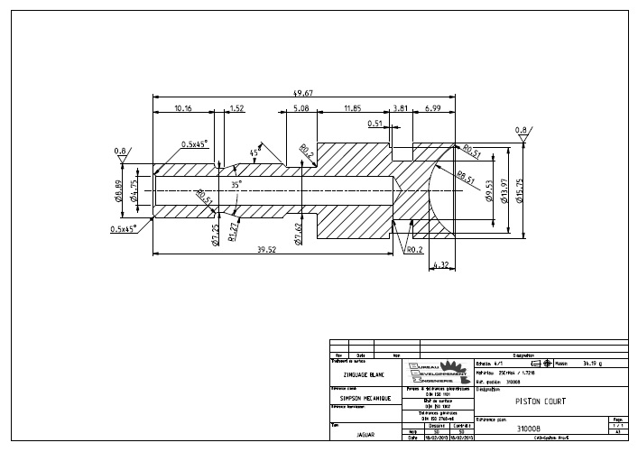
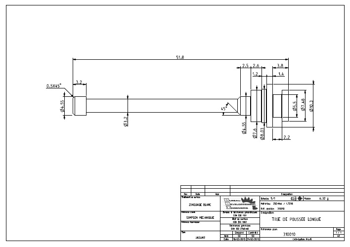
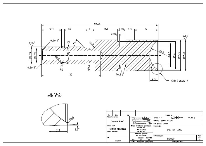
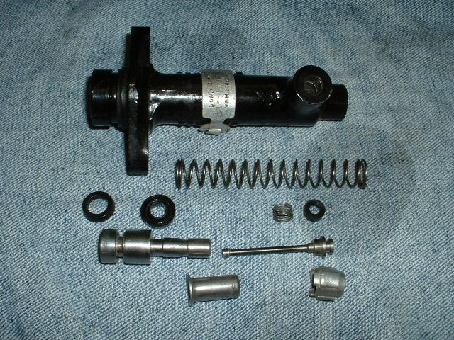
This is what the parts should look like :
The Front (lower) cylinder has a "Short" 50mm piston (so it can move further)
and a "Long" 52mm valve. Combined length 102mm.
The Rear (upper) cylinder has a "Long" 59mm piston (it has a shorter travel)
and a "Short" 42mm valve. Combined length 101mm.
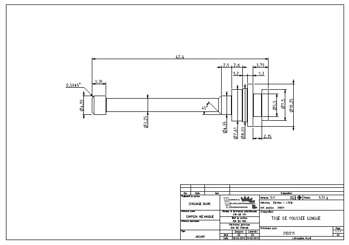
These are not Jaguar drawings but my own, based on the parts I measured ; many of the dimensional details and variations are actually irrelevant to the way the parts function and some are likely to be due to wear and manufacturing vagiaries - but the drawings will hopefully help identification.
NOW FOR THE HISTORY OF HOW WE GOT THERE ...........
There is an abundance of appalling bad-science and voodoo written about the brakes on the 3.8's. I therefore thought some readers might find light relief in discussing them in the hard light of physics and arithmetic. We don't even have to use mathematics. Here is my sixpence-worth, and whilst I'd be delighted to modify the text as a result of polite corrections, the spotting of mistakes, and the highlighting of aspects that may be peculiar to my car, let's stick to engineering principles rather than bar-talk. The oft-invoked nonsense regarding Front-Rear brake balance is probably a good place to start.
Here's as good an example of complete failure to understand Physics and Hydraulics as you'll find on the Forum, unfortunately still quoted as a reference source :
https://www.dropbox.com/s/9hzpaajjoce0w ... 1.pdf?dl=1
complete with such gems as :
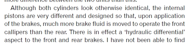
and :

which demonstrate absolutely NO grasp of the subject, hydraulic "differential" based on amounts of fluid being an inexistant concept save in the mind of the author, and completely irrelevant when both master-cylinders are of the same diameter and are attacked midway by the pedal effort.
Whilst it is clear that the Front brake cylinder should be different to the Rear (the piston and the rear spring-seat are different, such that the Front has a 9.5mm - 3/8" longer stroke), these differences make absolutely ZERO difference to the brake "balance".
To all intents and purposes, the 3.8 Front-Rear brake balance is determined by six things, all of them within the grasp of a half-bright O-level student with a grasp of Pascale's Law and a familiarity with Meccano.
1. Pedal bias
2. Master-Cylinder diameters
3. Caliper-Piston diameters
4. The Number of pistons per caliper
5. The Position of the caliper, which essentially means the "effective" Diameter of the disc
6. The Pad Compound
Point One - pedal bias
The first variable is the mechanical allotment of the brake pedal effort between the front and rear master cylinders, via the bias-bar and drop-link arrangement located in front of and below the Kelsey Hayes servo.
The servo itself is totally irrelevant to all our reasoning here since it just responds to the driver's effort on the pedal and adds a lot more.
Since this arrangement is largely invisible due to the cheeks of the pedal-box to master-cylinder housing, I built a replica minus the RH cheek-plate in order to study the behaviour of the different parts concerned.
I've labelled all the bits with names that seem to describe their function, and tried to refer to these consistently throughout the text.
FIG.1
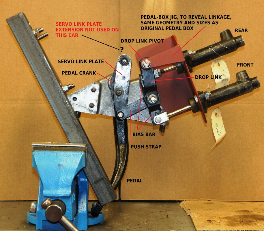
Please note that I don't actually use the Kelsey-Hayes servo, for reasons that are outlined here:
http://www.etypeuk.com/forum/viewtopic.php?t=3848
FIG.2
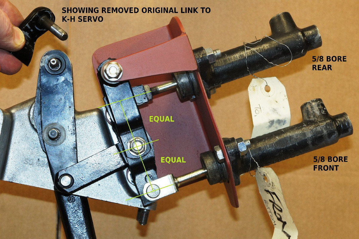
This shot shows the part that's missing on my car ; however, this makes absolutely no difference to the function and operation of the linkages and hydraulics. The first thing to notice is that the pedal effort is transmitted through the pedal crank to the servo link plate, and then into what I've called the push-strap for want of a better term.
This then pushes on the bias-bar via a pivot bolt that is exactly half-way between the two master-cylinder clevis pins, see Fig.2. There is, then, no mechanical bias via our 3.8 "bias-bar" since it attributes pedal effort 50/50 to the master-cylinder pistons, irrespective of how far one or the other has advanced. Each cylinder relies on the other one to "share" the pedal load, including when one or the other has failed, as we shall see, and the bias-bar - via its central pivot - keeps the mechanical advantage identical Front - Rear wherever the pistons may actually end up.
With identical 5/8" bore master-cylinders, then, we automatically get the same line-pressure in both Front and Rear circuits.
Thus Point One "pedal bias" is irrelevant, since there is none.
Irrelevant too is Point Two - master-cylinder diameters, since they are the same.
Point Three concerns the respective front/rear caliper-piston diameters ; the original calipers have 2 - 1/8" diameter Fronts (hence 17/8 to work the fractions later), 1 - 3/4 " Rears (and 7/4 or 14/8 for the arithmetic), so for a given line pressure (the caliper's clamping force being determined by the surface area of its pistons) the fronts produce (17/14) squared more grip on the pads, this shakes out to 1.47 times more.
Point Four there are the same number of slaves Front-Rear (4 each) so we can ignore this parameter.
Point Five is the radius at which that effort is applied to the discs ; a bigger disc requires less grip to produce the same torque (effort x distance). If we take the E-Type discs of 11" Fronts and 10" Rears, and consider that a 2" deep pad applies its effort 1" inboard from the edge, we get operating radii of 4.5" on the Front and 4" at the Rear.
So the product of Points Three (caliper grip) and Five (caliper position) give ( 17/8 )? divided by ( 7/4 )?, multiplied by 4.5 / 4.0, which in my book works out at a result of 1.65 times more braking on the front.
A quick bit of algebra converts this into a Front to Rear split of about 62% Front to 37% Rear.
Point Six is the coefficient of friction determined by the pad compound used. Since we don't have reliable figures and every car uses different stuff, we shall asssume these are the same material at both the Front and the Rear.
(Note that pad size is ignored, as under a given load from the piston a bigger pad spreads that load more lightly, and vice-versa, so does not change the reasoning - only its capacity to not overheat and evacuate the calories.)
No amount of argument about seal-positions on pistons (totally irrelevant) or the length of the push-rods (a complete red herring) etc makes any difference to these fundamental reasonings.
HOWEVER !
The travel of the master-cylinders DOES matter for the simple reason that the brake-pads are always at a certain distance from the discs before the brakes are applied (due to discs running out of true, slop in wheel bearings, the pull-back effect of caliper-seals etc), and these gaps have to be taken up by pedal and master-cylinder movements before the pads hit the discs and braking can begin.
The increased travel of the 3.8 Front-brake cylinder (plus 9.5mm / 3/8") can be accounted for in terms such as these.
The Front discs are bigger (for a given slop, this gives 4.5/4.0 increased push-back), and for a given push-back the effect with bigger pistons is to push back more fluid - ( 17/8 )² divided by ( 7/4 )² more in fact, at the front, than at the back - and the Front discs on the E-Type are far less well supported than the Rears, more exposed to lateral loading etc, so run-outs will be bigger.
It can thus be calculated that it only requires an extra 0.008" movement of the Front pads (in comparison with the Rears) to use up the famous - and elusive ! - 9.5mm (3/8") extra piston-travel of the Front master-cylinder.
(Could someone check my mathematical gymnastics ? master-bore ( 5/8 )² divided by slave-bores 4 x ( 17/8 )², multiplied by master-cylinder stroke 3/8" ?)
CONFESSION
Like most people, apparently, my car has the wrong 1" - travel Front master-cylinder fitted, VBM.4706, rather than the 1 - 3/8" travel version VBM.4038, but before we get our knickers in a twist over this, I thought it might be interesting to understand what effect this might have ?
On my car, at least, at rest, the pedal-box looks like this :
FIG.3
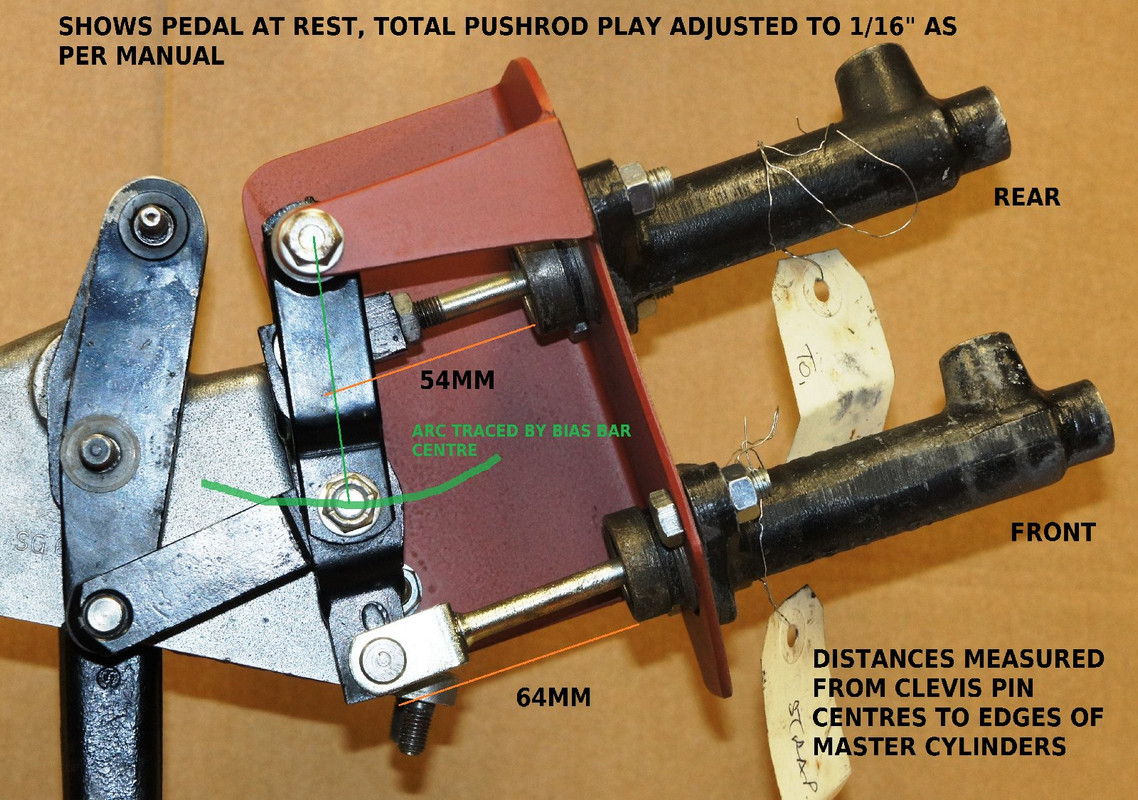
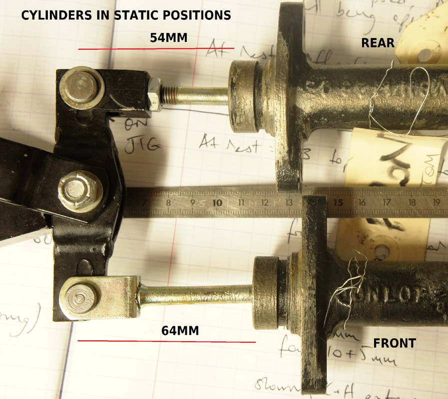
Note that the drop-link pivots around the top bolt, dictating the arc which the bias-bar centre-bolt follows, and the master-cylinder-to-clevis-pin lengths are Rear 54mm and Front 64mm, which - probably no surprise - is the same 10mm difference as their original travels, as we shall see.
This difference in lengths - on my car at least - is confirmed in this shot, below
FIG.4
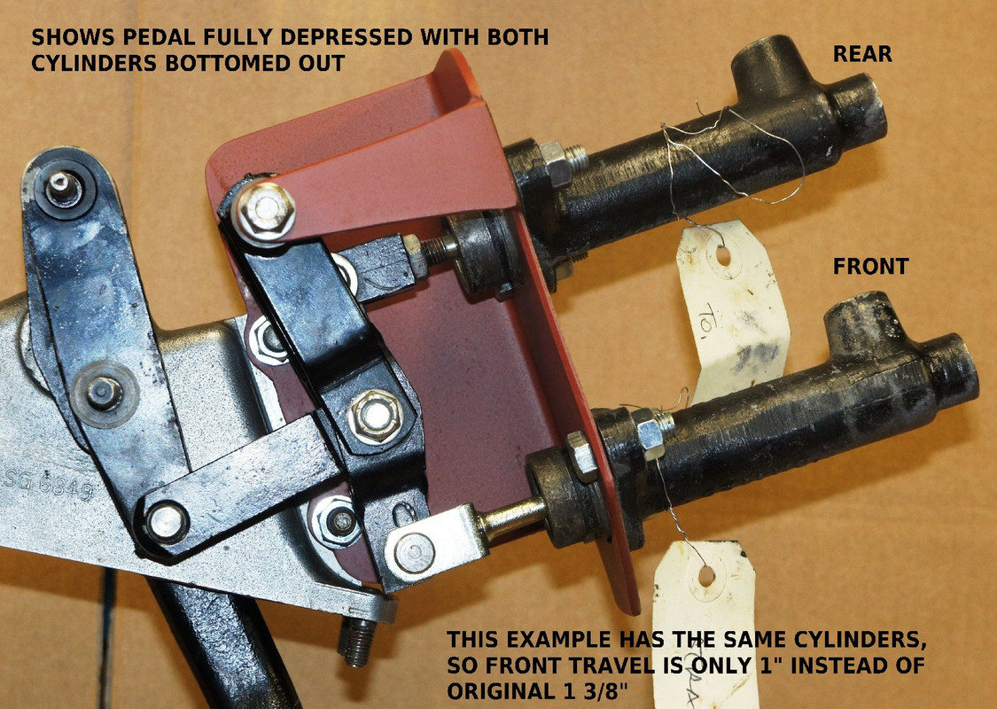
Just to see what happens were either or both circuits to fail, here (below) is the maximum-pedal-travel position, with both cylinders at the end of their travels. The pedal isn't touching anything inside the pedal box, and the linkages are still perfectly happy.
FIG.5
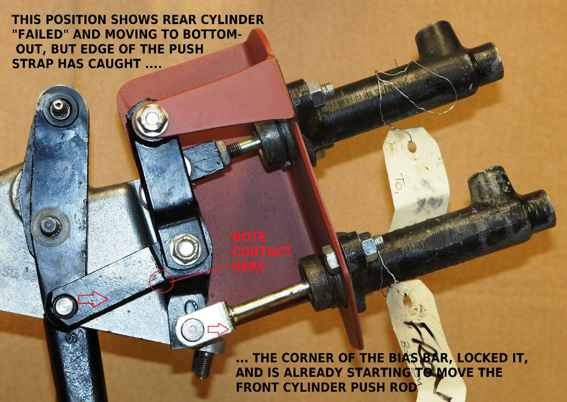
This one (below) shows the Rear "collapsed", big fluid-loss for example, with the Front continuing to function - even if the rear clevis were to fall out - because the push-strap edge hits the lower end of the bias-bar and locks the whole thing up. So the Fronts continue to work unabashed.
FIG. 6
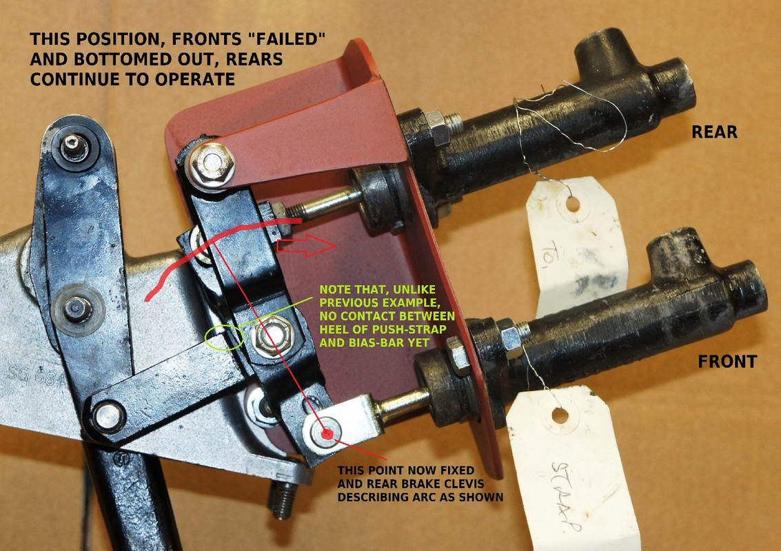
This (below) shows the Fronts "failed", imagine no-fluid and bottomed out, with the bias-bar now rotating around the Front master-cylinder's clevis-pin, and the Rears continuing to function.
NOTE HOWEVER, that in this case there is NO contact between the heel of the push-strap and the bias-bar as there was in the "Rears failed" example - maybe because the travel of the Front cylinder is shorter than it was designed to be.
This might mean that the pedal would go further to the floor before the Rears started to bite .. but would make no difference to the ultimate braking available on the Rears.
FIG.7
In conventional operation I have simulated two situations, the first (below) with just the Front moving by 10mm, to take up the hypothetical Front-Rear difference in travel due to pad retraction.
FIG.8
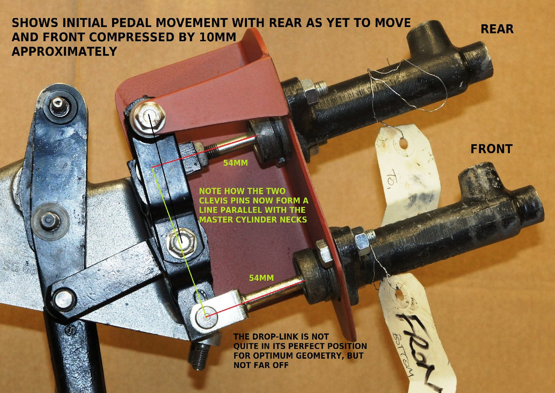
The clevis-pins are now on a line parallel with the master-cylinder necks, although the drop-link is not quite in the optimized position that would set the bias-bar centre bang in-between the master-cylinder bores. If we now depress the pedal further, moving Front and Rear cylinders an extra 5mm, which might correspond to a typical hard-braking situation (ie 10mm of extra slack on the fronts, plus an extra 5mm on both) then we get (below) a pretty-much optimized geometry for the whole set-up.
FIG.9

Here, then, side-loads on the ball-ends of the operating push-rods are reduced to a minimum, which is the whole point of the mechanism we're studying, and one might reasonably conclude that this was Jaguar's intention - maximum braking effort occurring at the position in which all the geometry "clicked" into the optimum alignments of the mechanical linkages ?
CONCLUSION ?
At this point I've called "hard-braking", we've only used up 5/25 or 20% of the Rear-brake travel, BUT 15/25 or fully 60% of the wrong (short 1") Front-brake cylinder's travel.
If the correct 1 - 3/8" Front were fitted, in this position my car would have used only about 40% of its stroke, leaving a much bigger margin of safety to cope with excessive pad pull-back, water in the brake circuit etc.
Furthermore, it seems likely that with the correct longer-travel Front master-cylinder fitted, even if the Front clevis-pin were to fall out, the famous contact between the push-strap shoulder and the bias-bar would be re-established and the Rears continue unperturbed.
So this longer 1 - 3/8" master-cylinder makes NO DIFFERENCE WHATSOEVER unless you lose all the fluid in the rear circuit, and even then you might just have to take a second pump on the pedal.
It certainly makes no difference whatsoever to the Front-Rear bias.
CAVEAT
I would suggest that it's not enough to just modify internal components (with a shorter piston, and a modified spring-support) to give 3/8" extra travel without completely understanding the interaction between those parts and the shuttle valve that shuts off the fluid-ingress port at the end of the cylinder, since the action of that valve depends on its position within the piston/spring-support interface.
WHICH LEADS ME TO MAKE THE FOLLOWING APPEAL !
If anyone can supply an example of the "longer-travel" master-cylinder internal components, of guaranteed provenance, or tell me where I can find a supplier that is familiar with these nuances (I've looked to no avail) then I will fit them to the mock-up and carry out the same analysis as with my "wrong" one, publish the results, and then get them drawn up so we can commission the necessary parts to convert "shorts" to "longs".
And nail, once and for all, the myths.



 Sorry, but it is


