Body repair jig

Technical advice Q&A

Topic author
unclerob
Posts: 41
Joined: Mon Aug 12, 2013 3:08 pm
Location: kent, uk

#1 Body repair jig

Post by unclerob » Tue Aug 20, 2013 3:19 pm

Hello all, a couple of weeks ago I bought a seriously rusty Series 1 2+2 that I've begun writing about in the restoration section.
Essentially very little of the underside of the car is going to remain, so rather than take the route of replacing some bits at a time and building in errors I'm going to make a rigid jig that should (hopefully!) hold everything in alignment.
I do know that one can be hired in the Chester area but prefer to make my own.
I started today, and progress so far has been to make the main frame using 80x40 box section doubled up in an 'L' arrangement, so as to get sufficient strength and have access for welding. As yet, its only tack welded as I haven't worked out how to fully weld (got a bit hot and sweaty and decided sitting at computer preferable!)
There will be trunnions at each end so that it can be rotated to different angles.
At the rear will be fittings that bolt to the bodyshell in the same way as the diff cage and additional places to locate the radius arm mounts.
The front 'saddle' I am making adjustable so it can also be used for coupes and convertibles, this will clamp to the bulkhead firstly at the lower/inner 'a' frame mounts (using spacer blocks so they don't distort) and also to at least 2 and maybe 4 other places on the bulkhead.
The basic idea being that if I get all of the original Jaguar suspension mounting places etc right on the jig then the bodyshell should come out ok as well...
A bit later on I plan to add some other extensions to the basic jig to aid the fitting of the sills, jacking points etc
Any suggestions, pictures of other ones, or bodyshop drawings greatly appreciated!!

Image
New owner of series1 2+2 4.2 auto (in bits!)

Link:
BBcode:
HTML:
Hide post links
Show post links


christopher storey
Posts: 5698
Joined: Sun Mar 09, 2008 3:07 pm
Location: cheshire , england
Great Britain

#2

Post by christopher storey » Tue Aug 20, 2013 5:57 pm

Have a word with Andy Rayner at Hutsons, 01274 669052, who can probably send you drawings/photos of the jigs they use , and will certainly give you advice on the best approach . Although most of their work is SWB cars he did a 2+2 about 2 years ago. Neil 4444 on this forum is having a car done by them and if you look at some of his recent posts there were pics. Also if you look on xkedata at 1E 20357 you will see how they tackled my FHC. Incidentally, a lot of the time they did not brace the car in the conventional way , but it still turned out to have some of the best panel fit I have seen ( but then of course they make most of the panels in the first place )

BTW, I think that tube reinforcement of the sort that you referred to is totally unnecessary. When properly built and not rotten these cars are very stiff indeed, particularly in the closed versions, and the only additional reinforcement which I have seen which may assist is that on the SWB cars people use a 3rd stiffener in the sills, but frankly it is not needed

Link:
BBcode:
HTML:
Hide post links
Show post links


Topic author
unclerob
Posts: 41
Joined: Mon Aug 12, 2013 3:08 pm
Location: kent, uk

#3

Post by unclerob » Tue Aug 20, 2013 7:08 pm

Ok, Christopher, thank you for that, I have managed to find a lot of working drawings for SWB cars and have all I need for the rear end on which work begins tomorrow...
I'll take on board what you say about tube reinforcement, I was thinking it wasn't really necessary on a closed car but a possible benefit on an open one....so more along the lines of an experiment really!
Impressed by your judgement the other day regarding bulkhead distortion, its only today that I've found just how misaligned it is, almost an inch! I've found signs of a fairly major accident repair to the passenger side rear which is probably the root cause.
New owner of series1 2+2 4.2 auto (in bits!)

Link:
BBcode:
HTML:
Hide post links
Show post links

User avatar

Heuer
Administrator
Posts: 15157
Joined: Sat Mar 01, 2008 5:29 pm
Location: Nottinghamshire
Great Britain

#4

Post by Heuer » Tue Aug 20, 2013 8:20 pm

This has the makings of the best thread ever on the Forum ................. keep it up 'unclerob'! Can we call you Rob by the way?
David Jones
S1 OTS OSB
1997 Porsche 911 Guards Red
2024 Lexus LBX

Add your E-Type to our World Map: http://forum.etypeuk.com/viewtopic.php?f=1&t=1810

Link:
BBcode:
HTML:
Hide post links
Show post links

User avatar

GSR 54D
Posts: 281
Joined: Wed Dec 03, 2008 1:17 pm
Location: Surrey
Great Britain

#5

Post by GSR 54D » Tue Aug 20, 2013 9:21 pm

I have made a point of checking this and "restoration stories" thread frequently particularly as it's moving so fast "rear end tomorrow" a man with time on his hands!!

Incidentally, unclerob, it may be a 2+2 but don't let this be a disappointment it is still a series 1 which makes it quite rarer than series 1 FHC & OTS.
Correct me if I'm wrong but over the past 5 years+ I haven't seen many series 1 2+2 's for sale and particularly "well restored" ones. I guess the majority of these cars went to the scrap heap first being some 30+ years ago when desirability was low and it wasn't even cost effective to keep them in a garage.
However this has made the series 1 2+2 a little more unique so good luck.

John H.

Link:
BBcode:
HTML:
Hide post links
Show post links


Topic author
unclerob
Posts: 41
Joined: Mon Aug 12, 2013 3:08 pm
Location: kent, uk

#6

Post by unclerob » Tue Aug 20, 2013 9:36 pm

Thanks for those kind comments, and yes Rob is fine, acquired a new niece a few days so picked the username on a whim....
I'm afraid though that this might be a little start and stop, I'm waiting for parts for another job and will have to go back to it when they arrive....
Hoping to have enough time to get the basics done, leave the straightforward bits like the rotating part, stops etc, so I can try the shell in place at the weekend.
New owner of series1 2+2 4.2 auto (in bits!)

Link:
BBcode:
HTML:
Hide post links
Show post links


steve3.8
Posts: 459
Joined: Sun Mar 22, 2009 9:12 pm
Location: nottinghamshire,uk
Great Britain

#7

Post by steve3.8 » Wed Aug 21, 2013 11:37 am

Hi Rob,

I like your enthusiasm and you will need lots of it to see the restoration to the end , this may help you , a few years ago I made a rollover jig that locates on the rear cage mountings and the front frame mounts , my thinking also was to keep the body tub parallel and avoid any twisting during repair . I took all the dimensions from the workshop manual , the front and rear jigs were bolted to the longitudinal sections and not welded to aviod distortion , they have support tubes inside the box sections to stop the section crushing when bolted up
To make the front bulkhead jig I first made what was basically an mdf box with no lid or front pre drilled to the front frame dimensions , this enabled the sections to be bolted and clamped in situ then tacked together with more accuracy before fully welding .
The picture on my car is before I started cutting away the previous owners patched repairs.


The scanned drawings are for the swb , if you are building a rotating jig the roofline is higher on the 2+2 so the axis point may differ ? to give ground clearence .

Image
Image
Image
Image
MDF BOX
Image
Steve3.8

64 3.8 fhc, 67 4.2 fhc

Link:
BBcode:
HTML:
Hide post links
Show post links

User avatar

Simonpfhc
Posts: 766
Joined: Mon Aug 27, 2012 12:38 pm
Location: Surrey
Great Britain

#8

Post by Simonpfhc » Wed Aug 21, 2013 2:48 pm

Hi Steve,

That's an impressive jig you've built there! If this was ' a few years ago' does that mean you have now finished with it? If you have, I would be very interested in buying/renting it from you :-)

Let me know.

Cheers.
Simon
62 3.8 FHC
91 Porsche 928GT
Find me on Instagram and Facebook @oldcarfixer

Link:
BBcode:
HTML:
Hide post links
Show post links


Topic author
unclerob
Posts: 41
Joined: Mon Aug 12, 2013 3:08 pm
Location: kent, uk

#9

Post by unclerob » Wed Aug 21, 2013 7:12 pm

Hi Steve, lovely jig....mines going to be very similar...even down to the tube sizes! Am planning additional fittings to the radius arm mounts and also the lower inner front frame mounts....
I can't quite see in the photo but are your main rails touching the floorpan or did you leave a gap? I'm planning a 20mm one on mine in case I mask something.
Take your point about distortion but I find if you work out the sequence and direction and mark it all up with chalk first it usually comes out ok, I did the main frame today and came out fine.
Also, not yet sure about how far it will rotate, if I make it so it can turn completely I'm thinking that reaching inside the body will be awkward because of the height, maybe it would be better to limit the turn to around 150 degrees...
You're right re the enthusiasm bit, I was underneath it today taking bits off....earlier on I said something about maybe at least the roof was useable....in jest....buts it coming horribly true!
Had also vaguely wondered why a previous owner had left chopped off bits of radius arms attached to the body but already taken the bolts out....I know now!!
New owner of series1 2+2 4.2 auto (in bits!)

Link:
BBcode:
HTML:
Hide post links
Show post links


steve3.8
Posts: 459
Joined: Sun Mar 22, 2009 9:12 pm
Location: nottinghamshire,uk
Great Britain

#10

Post by steve3.8 » Wed Aug 21, 2013 10:13 pm

Rob ,

The main rails are approx 60mm off the floor and 20mm off the footwells
My jig turns 360? , being able to turn the tub to 180? is preferable for fitting and welding the floors and cills , also pretty much most of the other panels.

One thing I should have done with hindsight is fit spockets and chainset for more control and safety during rotation , when you start removing several panels from one side of the car it creates a weight unbalance and needs 2 people to operate safely , ie one to turn and one to tighten the 4 caphead bolts on the pivot tubes .

Simon ,

I built the jig about 3? years ago and started the panel work , sorry but the car is
?still? on the jig and pushed in a corner , I bought another E and an elan which has clogged up my garage space and slowed progress , back on it soon though as I?ve just built another garage .
Steve3.8

64 3.8 fhc, 67 4.2 fhc

Link:
BBcode:
HTML:
Hide post links
Show post links

User avatar

Simonpfhc
Posts: 766
Joined: Mon Aug 27, 2012 12:38 pm
Location: Surrey
Great Britain

#11

Post by Simonpfhc » Thu Aug 22, 2013 6:26 am

No problem Steve, thanks. You have quite an impressive collection there. Good luck with the garage build - sounds like you are going to need the space :-)

Cheers.
Simon
62 3.8 FHC
91 Porsche 928GT
Find me on Instagram and Facebook @oldcarfixer

Link:
BBcode:
HTML:
Hide post links
Show post links


Topic author
unclerob
Posts: 41
Joined: Mon Aug 12, 2013 3:08 pm
Location: kent, uk

#12

Post by unclerob » Thu Aug 22, 2013 6:53 pm

A bit more progress today, made the front upper mounting and then attached it to the jig....
The straight edge of the mounting showed how much distortion there is in the bulkhead, about 20mm on the passenger side, it pulled up easily enough when I tightened the bolts but just in case its needed I've started building a heavily reinforced post at the front of the jig so I can doing any pulling with a porta power.
Hadn't thought at all about the turning problem....it could easily turn into a sort of expensive fairground ride! Had just planned steel pins at either end....will have to think, maybe some kind of friction clamp system so it stays under control!
Took all the wiper parts, water pipes out today....thats fun isn't it? Really looking forward to putting them back in!

Image

Some more pictures of jig in photobucket by the way...
New owner of series1 2+2 4.2 auto (in bits!)

Link:
BBcode:
HTML:
Hide post links
Show post links


Topic author
unclerob
Posts: 41
Joined: Mon Aug 12, 2013 3:08 pm
Location: kent, uk

#13

Post by unclerob » Fri Aug 23, 2013 5:30 pm

Some more progress today, a little more to do at the back end (I've left the cradle over wide so I can take paralell measurements by the way) and can then try the bodyshell in it....

Image

After I've tried it out, and made any changes needed I'll then add the turning frame.
New owner of series1 2+2 4.2 auto (in bits!)

Link:
BBcode:
HTML:
Hide post links
Show post links

User avatar

vee12eman
Posts: 821
Joined: Mon Nov 26, 2007 7:14 pm
Kiribati

#14

Post by vee12eman » Fri Aug 23, 2013 11:16 pm

Hi Rob,

Like many I am watching this post with great interest, I would love to be doing this all again. Some years ago I went through a similar process, my bodyshell was not quite as bad, not having the distortion you have described. As a result I only built a simple rotisserie, without the "jig" aspect to the design. As such I can't advise you on exact dimensions, but there are a few things which might help you.

Hinges - you appear to have a similar idea to mine - round posts which fit inside sleeves allowing rotation. This worked well and originally I was going to drill a series of holes to allow me to lock the car at 180, 80 and 45 degrees, but in the end it was much more helpful (and simple) to use a clamping system:

Image

With a nut welded to either side of the outer sleeve and a bolt screwed in, you can lock the car at any angle, a great help when welding as you can position the car at any optimum angle. Another advantage is that if the balance is not perfect, you can turn the car with some friction remaining (by not fully loosening the bolts), making it easier to control. I still drilled one hole to allow me to lock the car easily at the normal angle, also meaning the car was safe and solid if I moved it.

As to balance, you should be able to see that I positioned the car with the pivot point directly through the same level as the upper engine frame, the rear mount went straight into the rear number plate panel; which at that time seemed to be accepted practice. Most now make a jig as you are doing and the extra effort is probably well worth it. Now with my arrangement, balance was almost perfect and I was able to turn the car single handed with no problem, normally doing it from one end of the car or another, with a spanner on the bolt ready to lock it of at the angle required; back the bolts off until it just turns, spin the car and tighten the bolt. Your jig will add some weight under the car, although my car had a sunroof, so the roof was a little heavier at first (before removal). When I later removed the sun roof (including wooden frame) and the dash assembly and tailgate, all of which are above the pivot point, the car was still easy to turn. I also turned the car both with and without doors and tailgate fitted and never found any problem doing it. I think I might lower the pivots by a few centimetres, depending on the depth of your lower rails, so that the pivot line is around 5cm lower than the upper engine frames, but this is guessing and may not be necessary. I also recommend stiffening bars from the jig, down to the lower engine frame points - you can see them in the photo showing the hinge/bolt arrangement. I made mine without originally and the car moved about rather alarmingly on the initial test! Oh by the way, my car is a Series 3 FHC (correct designation!) but like all S3 FHC actually has a 2+2 shell pretty similar to your own, so balance points will be similar.

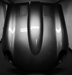
When completed I could do this:

Image
Another view couple of views:
Image

Image


When the main welding was finished I removed the posts (which had plates allowing them to bolt to the base frames), then added some framework allowing me to mount the car on the jig to allow build of the car. I built the front suspension with the car at a comfortable height and added a lot of the underside components like fuel and brake pipes. With the frames on wheels I could move the car at will and in fact I painted the car like this, allowing access under sills and boot floor:

Image

Also I sold mine for more than it cost to make, even without the jig fittings, so your work is a worthwhile investment, may even help you pay for parts later on when the body is finished!


(A couple of edits - more pictures here:

http://etypeuk.com/forum/viewtopic.php?t=385

Another site with helpful and even inspirational help, also showing a rotisserie - the original guide I based my design on:

http://mckennasgarage.com/xke/

And finally my XKE data page:

http://www.xkedata.com/cars/detail/?car=1S50097BW

Also make sure your pivot point is far enough forward to fit the sills which protrude forward from the bulkhead - easily overlooked)

Good luck and keep posting!

Regards,

Simon
Regards,

Simon
Series III FHC

Link:
BBcode:
HTML:
Hide post links
Show post links


Topic author
unclerob
Posts: 41
Joined: Mon Aug 12, 2013 3:08 pm
Location: kent, uk

#15

Post by unclerob » Sat Aug 24, 2013 9:55 am

Hi Simon, many thanks for taking the time to write, like you I'm enjoying making the jig a great deal but its easy to overlook some aspects and you've given me several things to think about....and just in time too!
I was intending to just use locking pins on the rotating part but the friction bolt idea combined with a safety pin will be much better.
I think the anomaly as regards pivot height is explained by the fact that my jig rails are 120mm deep, plus I have left a 21mm gap between their upper face and floor rails of the shell...the idea being I can then insert detachable sections of 40x20 box if/when needed. By calculation at least their position is on a mid point between the cars roof and the bottom of the jig rails.
I shall definitely be stealing your idea of making the pivots height adjustable, if I make the uprights from a pair of builders acrow props then it should be possible for 2 people to adjust the height quite easily...
The front 'saddle' that I'm making will also attach to the body at the lower mounts as you suggest....I've made it detachable for 2 reasons, so that it can be fitted onto the jig after the shell is in place but also so that the jig can be used on SWB cars....I very much doubt that I'll use it more than once and it'll take up way too much space to keep!
Good point about the sills, had a horrible sinking feeling for a moment but just checked all ok!!
At the rear end I will be adding legs that locate on the radius arm mounts (as much as for alignment as anything else) but looking at your car I get the impression they are further apart than mine...will look for some Series 3 drawings to check!
Hesitate to mention this in case people think I'm totally barmy but am now considering making a bonnet jig along the same lines!!!
Again, many thanks
New owner of series1 2+2 4.2 auto (in bits!)

Link:
BBcode:
HTML:
Hide post links
Show post links

User avatar

vee12eman
Posts: 821
Joined: Mon Nov 26, 2007 7:14 pm
Kiribati

#16

Post by vee12eman » Sun Aug 25, 2013 10:25 pm

Hi Rob,

No worries on the help front, anytime. Another thing I found useful was for the box section, which supports the pivots and is mounted on the uprights at either end, to be fairly large compared with the actual uprights themselves (you can see this in the photos of my original post). This allowed the change of height in stages by one person, one hole at one end at a time, the difference in size allowing the hinge box sections to pivot slightly relative to the uprights, though it sounds as if you have some different (and very workable) alternative ideas about the uprights. I just used a normal car jack and a strong support under it to lift/lower each end slowly, bit by bit. I wasn?t blessed with ready availability lots of strong guys available to help me raise/lower!

Another advantage was that the whole thing had a little flexibility if moving around on a rough floor (should you choose to put castors on the bases). It also meant they could move slightly when rotating the car, but with your fixed jig this probably isn?t necessary.

Regards,

Simon
Regards,

Simon
Series III FHC

Link:
BBcode:
HTML:
Hide post links
Show post links


Topic author
unclerob
Posts: 41
Joined: Mon Aug 12, 2013 3:08 pm
Location: kent, uk

#17

Post by unclerob » Mon Aug 26, 2013 9:09 am

Your suggestions and advice are much appreciated Simon. I suspect that, like me, you were thinking that on my jig the pivot axis was too high and the whole thing would be very hard to rotate and then suddenly very easy!! It wasn't until I saw your pictures of the height adjustment feature that I realised clearance didn't have to be an issue so have now altered this...typically it was one of the few parts of the jig I'd fully welded!
It should make things a lot easier in practice though....
I'm still undecided about how rigid to make the support part of the frame, (waiting for the shops to open tomorrow so I can get hold of a couple of the props I want to finish the job) but I think probably just a single beam to allow some flexibility...
New owner of series1 2+2 4.2 auto (in bits!)

Link:
BBcode:
HTML:
Hide post links
Show post links


Topic author
unclerob
Posts: 41
Joined: Mon Aug 12, 2013 3:08 pm
Location: kent, uk

#18

Post by unclerob » Wed Aug 28, 2013 6:48 pm

Had a free day today so the jig isn't too far from finished, I bought a pair of builders props so that there is about 450mm of height adjustment ...

Image

One more days work should see it finished....
New owner of series1 2+2 4.2 auto (in bits!)

Link:
BBcode:
HTML:
Hide post links
Show post links


Topic author
unclerob
Posts: 41
Joined: Mon Aug 12, 2013 3:08 pm
Location: kent, uk

#19

Post by unclerob » Thu Sep 05, 2013 7:11 pm

At last its finished! Took rather longer than planned partly because I kept on getting interrupted by having to do proper work and partly because the number of volunteers willing to lift the car on and off the jig, seemed (for some reason) to lose enthusiasm after 4 or 5 goes!
Anyway, it all fits, measurements have come out well within the limits I'd hoped for, its just had a coat of paint and tomorrow the body shell goes on for the last time....and likely to stay there for some while.

Image

The raising mechanism seems to be about right, it can be set so the car is low enough to work on and then lifted to allow the bodyshell to be fully rotated and clear the roof.
I've gone for the friction bolt idea in the pivots but also couldn't stop myself from adding a locking plate as well....just in case!
At the rear the body is attached to the jig by the diff cage mounting bolts and the radius arm mountings...have left the jig fittings lower there and machined 2 piece ally posts that can be detached in case access is needed.
Originally, I'd intended to cut away the wide crossbar (it was just there to make measuring more accurate) but in the end left it, thinking it might be some use whilst working on the rear wings....
The front mounting saddle bolts to the jig and attaches to the upper/outer engine frame mountings on the bulkhead and the torsion bar plate locating holes at the front of the gearbox tunnel.
Once I've started to do some work on the car I'll have a better idea if I've made any mistakes but as far as I can see it should be ok...
If anyone else is thinking of doing one of these, I'm happy to talk it through...also, many thanks for all the advice, measurements and suggestions I've received!!
New owner of series1 2+2 4.2 auto (in bits!)

Link:
BBcode:
HTML:
Hide post links
Show post links

User avatar

Mich7920
Posts: 777
Joined: Sun Mar 15, 2015 4:43 pm
Location: France
France

#20

Post by Mich7920 » Fri Jun 05, 2015 11:08 am

Hello Rob,
Could I have your help for my jig ?
I just bought a Serie I OTS which was " marvelous etc etc"...The result is that I'm obliged to change the all floor, the sills etc... Hello the surprises !!
So, I first need to built a jig and as others people, I think your's is the most elaborated and nearly as aesthetic than a E Type. Ok I exaggerate a little but looking at the end of the box, the cuts, the idea of the builder props and so on, it demonstrate your way of thinking.
To end with the flattery, thanks for all the photos!
My questions are :
How long are the box welded in "L"
Are they 80x40x2 ?
How did you manage the difference in hight between the floorpan and the radius arm mount to well weld your fightings ?
As it's an OTS I thing it will be better to fix a box from the front to the upper floor thought the clutch/box housing. What do you think about this ?
I think also that it's more easy to work in each instead of mm.
That's all for the moment.
Best regards
Michel
Michel
1965 E Type FHC - On the road / 1963 E Type OTS - on the road after Angus Restoration

Link:
BBcode:
HTML:
Hide post links
Show post links

Post Reply Previous topicNext topic