


It was a Lucas LR384 - the model fitted to a UK spec XJS in mid to late 1980s. The bracket was custom made out of 6mm angle iron. I have some pictures if you want to pm me your email address, but no great detail without dismantling it from the car. I also fabricated a heatshield for it and a substantial earthing strap.
The Butec is a more than capable unit and the controller is easy to rebuild. The most likely cause of problems with these units are the connectors and th3e wiring - the other components are never under really operating past their limits on a standard car. I only went the over specified route because I have installed coil pack ignition, fuel injection and lpg in my car, all of which mean it consumes more power than before.
kind regards
Marek
Alternator with integrated regulator
#42
You can use pretty much anything you want in the smog pump position - you then make an alternator bracket to match. I've only gone with this alternator because it came free with the rest of an XJS that I bought for ?120.
kind regards
Marek
kind regards
Marek
| Link: | |
| BBcode: | |
| HTML: | |
| Hide post links |
#43
Must have been one hell of a car for that. I'm guessing the alternator was the only component worth saving??
Andrew S
'73 S3 COUPE, '15 Ford XR6
'73 S3 COUPE, '15 Ford XR6
| Link: | |
| BBcode: | |
| HTML: | |
| Hide post links |
-
 Heuer
Heuer
Topic author - Administrator
- Posts: 15173
- Joined: Sat Mar 01, 2008 5:29 pm
- Location: Nottinghamshire

#44
In my search for a small lightweight alternator I found the Cambridge Motorsport 'Edge Performance' 60amp is an excellent choice. Weighs 3.25 kg and hugely reliable.

However it does cost ?250 + VAT. But after a great deal of research I suggest it is a re-badged Denso 19630-64013 (it is used on John Deere tractors amongst other things) and new examples seem to be selling for between ?20 and ?50 on eBay as this one did - http://tinyurl.com/nkp69ho:


Unfortunately I had to buy the Edge version to understand what the core product was Still, others will benefit.
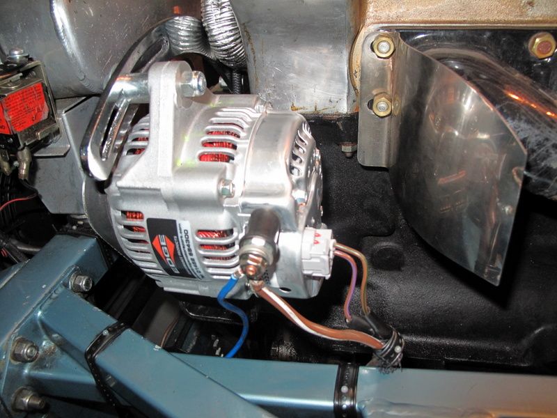
Works superbly, removing the belt is a doddle, half the weight/size and 60amps hot output. I used the brown/purple switched live to the connector centre terminal, the brown/green warning light 'earth' to the connector top terminal and the brown/white battery feed to the power out post terminal; the thick blue wire going to the battery terminal post is for the headlamp upgrade. You will need the special oval connector plug but it is readily available. The shaft is 17mm rather than the Lucas 19mm so you need a bit of 19mm tubing (1mm thick) to act as a shim on the pulley.
However it does cost ?250 + VAT. But after a great deal of research I suggest it is a re-badged Denso 19630-64013 (it is used on John Deere tractors amongst other things) and new examples seem to be selling for between ?20 and ?50 on eBay as this one did - http://tinyurl.com/nkp69ho:
Unfortunately I had to buy the Edge version to understand what the core product was
Works superbly, removing the belt is a doddle, half the weight/size and 60amps hot output. I used the brown/purple switched live to the connector centre terminal, the brown/green warning light 'earth' to the connector top terminal and the brown/white battery feed to the power out post terminal; the thick blue wire going to the battery terminal post is for the headlamp upgrade. You will need the special oval connector plug but it is readily available. The shaft is 17mm rather than the Lucas 19mm so you need a bit of 19mm tubing (1mm thick) to act as a shim on the pulley.
Last edited by Heuer on Sat Oct 25, 2014 1:53 pm, edited 8 times in total.
David Jones
S1 OTS OSB
1997 Porsche 911 Guards Red
2024 Lexus LBX
Add your E-Type to our World Map: http://forum.etypeuk.com/viewtopic.php?f=1&t=1810
S1 OTS OSB
1997 Porsche 911 Guards Red
2024 Lexus LBX
Add your E-Type to our World Map: http://forum.etypeuk.com/viewtopic.php?f=1&t=1810
| Link: | |
| BBcode: | |
| HTML: | |
| Hide post links |
#45
Visiting Stoneleigh yesterday and looking for a replacement Alternator for my lightweight rep which has an XJ6 series one alternator 60 amps I believe installed at present. I found traveling back from Goodwood last September in the pouring rain with lights on full beam and the windscreen heater on I was showing less than 12 v on the voltage meter. When the screen heater was turned off all was normal. At stoneleigh on the Fosseway stand they had an 80 Amp alternator and after discussion I purchased it. When fitted I will report on how the system copes with this high output alternator. Do any of the forum members use the heated front screen, as ask because it is excellent?
Kind Regards John
| Link: | |
| BBcode: | |
| HTML: | |
| Hide post links |
-
Heuer
Topic author - Administrator
- Posts: 15173
- Joined: Sat Mar 01, 2008 5:29 pm
- Location: Nottinghamshire
#46
Simply a case of adding up the total current draw. By my calculations:
Lights (full beam and sides) = 16 amps
Heater motor = 7 amps
Wipers = 5 amps
Ignition = 2 amps
Total = 30 amps. No idea what a heated front screen draws but it can't be 30 amps surely? Maybe worth putting a meter on the entire system and seeing what it draws. Could be a failing battery or alternator was the problem.
David Jones
S1 OTS OSB
1997 Porsche 911 Guards Red
2024 Lexus LBX
Add your E-Type to our World Map: http://forum.etypeuk.com/viewtopic.php?f=1&t=1810
S1 OTS OSB
1997 Porsche 911 Guards Red
2024 Lexus LBX
Add your E-Type to our World Map: http://forum.etypeuk.com/viewtopic.php?f=1&t=1810
| Link: | |
| BBcode: | |
| HTML: | |
| Hide post links |
#47
I agree with your calculations David also add to the list a Pacet electric rad fan which was running regularing due to heavy traffic at the time. I will take your advice and check the total current draw with every thing on. The Alternator was fitted prior to my ownership hence the unknown history. The only data from the data plate is: CA600IR, 3280 and SK1 (means nothing to me I'm afraid and no manufacturer's name either?)
Kind Regards John
| Link: | |
| BBcode: | |
| HTML: | |
| Hide post links |
-
Heuer
Topic author - Administrator
- Posts: 15173
- Joined: Sat Mar 01, 2008 5:29 pm
- Location: Nottinghamshire
#48
I made the assumption if you were running on full beam the cooling fan would not be required! But even so the standard fan only draws 6 amps, less for something like a Coolcat. Your current alternator is a Lucas item (aka LR460) used on Massey Ferguson tractors and various Fords - 70amp max output, internally regulated, although some vendors list it at 55amps which is the average output. Looking at the output graph it delivers maximum current above 4,000 alternator rpm which could be where your problem lies. Depending on the alternator/engine rpm ratio you might find at 2,000 rpm cruise you are only getting 50amps, 20 amps at idle:
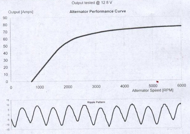
People forget an alternators output is still dependant on revs much like a dynamo although not as compromised. Pulley size is the determining factor here - need to measure crank pulley vs alternator pulley (2 3/8") to get the ratio. Because high output alternators have a very steep idle performance curve bigger is not always better - at tick-over it may not be charging. Output will also decrease as temperature increases so you need to find out what the 'hot' output is. For example the Denso unit is rated at 60amp 'hot' which means when cold it will output nearer to 80amps.
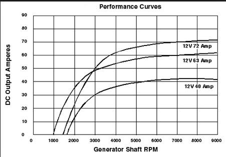
People forget an alternators output is still dependant on revs much like a dynamo although not as compromised. Pulley size is the determining factor here - need to measure crank pulley vs alternator pulley (2 3/8") to get the ratio. Because high output alternators have a very steep idle performance curve bigger is not always better - at tick-over it may not be charging. Output will also decrease as temperature increases so you need to find out what the 'hot' output is. For example the Denso unit is rated at 60amp 'hot' which means when cold it will output nearer to 80amps.
Last edited by Heuer on Tue Apr 01, 2014 6:16 pm, edited 3 times in total.
David Jones
S1 OTS OSB
1997 Porsche 911 Guards Red
2024 Lexus LBX
Add your E-Type to our World Map: http://forum.etypeuk.com/viewtopic.php?f=1&t=1810
S1 OTS OSB
1997 Porsche 911 Guards Red
2024 Lexus LBX
Add your E-Type to our World Map: http://forum.etypeuk.com/viewtopic.php?f=1&t=1810
| Link: | |
| BBcode: | |
| HTML: | |
| Hide post links |
#49
Many thanks David where do you get all this info from?
Kind Regards John
| Link: | |
| BBcode: | |
| HTML: | |
| Hide post links |
-
Heuer
Topic author - Administrator
- Posts: 15173
- Joined: Sat Mar 01, 2008 5:29 pm
- Location: Nottinghamshire
#50
Someone asked about the adjuster bracket I used. I could find nothing suitable in the UK so bought one of these from eBay US for $12 + $17 shipping:

http://tinyurl.com/phdosnq
Needed to cut 4" off the length, chamfer the end and drill a hole.
One other point: when calculating the load on the electrical system I forgot to say you need to add 3amps for energising the alternator coil.
http://tinyurl.com/phdosnq
Needed to cut 4" off the length, chamfer the end and drill a hole.
One other point: when calculating the load on the electrical system I forgot to say you need to add 3amps for energising the alternator coil.
David Jones
S1 OTS OSB
1997 Porsche 911 Guards Red
2024 Lexus LBX
Add your E-Type to our World Map: http://forum.etypeuk.com/viewtopic.php?f=1&t=1810
S1 OTS OSB
1997 Porsche 911 Guards Red
2024 Lexus LBX
Add your E-Type to our World Map: http://forum.etypeuk.com/viewtopic.php?f=1&t=1810
| Link: | |
| BBcode: | |
| HTML: | |
| Hide post links |
-
 Hubert Dallard
- Posts: 30
- Joined: Thu Aug 25, 2011 1:43 pm
- Location: Carri?res sur Seine (France)

#51
Hello David
I ve found a Denso 19630 but I would like to keep the control box. Could you explain me where I have to connect the top and the center terminal on the control box?
Many thanks,
Hubert
I ve found a Denso 19630 but I would like to keep the control box. Could you explain me where I have to connect the top and the center terminal on the control box?
Many thanks,
Hubert
Hubert Dallard
S1 FHC 3,8l 1964
S1 FHC 3,8l 1964
| Link: | |
| BBcode: | |
| HTML: | |
| Hide post links |
-
Heuer
Topic author - Administrator
- Posts: 15173
- Joined: Sat Mar 01, 2008 5:29 pm
- Location: Nottinghamshire
#52
Hubert
You can leave the original control box in place and wire as follows:
Brown/white - alternator screw post
Brown/Purple - centre terminal on alternator plug
Brown/Green - top terminal on alternator plug
The on-board regulator will do all the work so the car regulator does not need to cut-in. You could always bridge the Brown/Green and Brown/Purple contacts on the car regulator with a short jumper lead if you wanted to make sure it never operates.
Last edited by Heuer on Sun Dec 21, 2014 2:53 pm, edited 1 time in total.
David Jones
S1 OTS OSB
1997 Porsche 911 Guards Red
2024 Lexus LBX
Add your E-Type to our World Map: http://forum.etypeuk.com/viewtopic.php?f=1&t=1810
S1 OTS OSB
1997 Porsche 911 Guards Red
2024 Lexus LBX
Add your E-Type to our World Map: http://forum.etypeuk.com/viewtopic.php?f=1&t=1810
| Link: | |
| BBcode: | |
| HTML: | |
| Hide post links |

#53
I believe the wide mount base mini alternator depicted on page 3 in this string was originally used on the mid-80's Suzuki Samurai (U.S.). A rebadged 55-60 amp unit is offered as an option with the air conditioning kit from a well known supplier.
Eric
| Link: | |
| BBcode: | |
| HTML: | |
| Hide post links |
-
Hubert Dallard
- Posts: 30
- Joined: Thu Aug 25, 2011 1:43 pm
- Location: Carri?res sur Seine (France)
#54
David,
does it mean ? :
Brown/white: B connector of the control box
Brown/purple & Brown/green to the D connector with a jumper between B & D
Nothing connected to the W/L of the control box
is it right?
Thank you,
Hubert
does it mean ? :
Brown/white: B connector of the control box
Brown/purple & Brown/green to the D connector with a jumper between B & D
Nothing connected to the W/L of the control box
is it right?
Thank you,
Hubert
Hubert Dallard
S1 FHC 3,8l 1964
S1 FHC 3,8l 1964
| Link: | |
| BBcode: | |
| HTML: | |
| Hide post links |
-
Heuer
Topic author - Administrator
- Posts: 15173
- Joined: Sat Mar 01, 2008 5:29 pm
- Location: Nottinghamshire
#55
Hubert
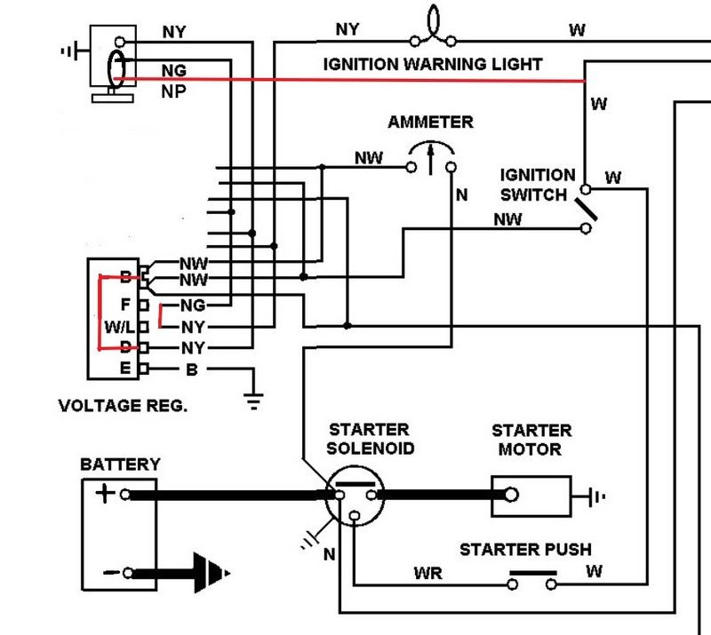
I assume you are converting from Dynamo to Alternator and if so you have already changed the car from +ve to -ve earth? If so this is the standard wiring diagram (I have erased the RB310 regulator for clarity):
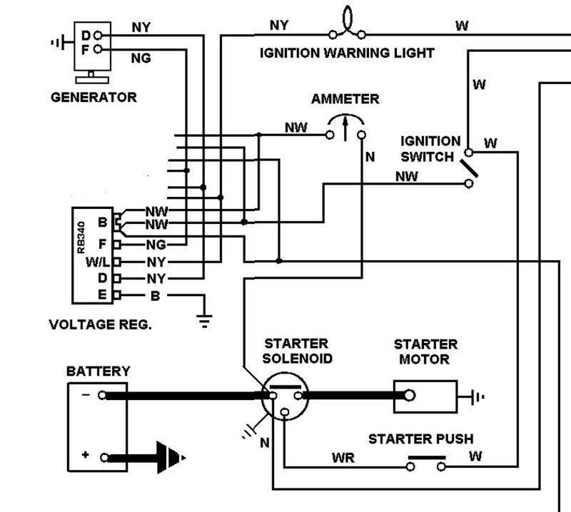
Not done one of these before but I suggest you start by disconnecting the battery.
Read Ray Livingston's article on JCNA before starting: http://www.jcna.com/library/tech/tech0018.html Remove the regulator and drill out the two rivets holding the case closed. You can replace them with nuts and bolts later. I will use Ray's description and photos and adapt the instructions to suit the Nippondenso and original wiring colours.

1. Establish a permanent connection from the alternator output terminal to the battery, through the heavy-gauge brown/yellow and brown/white wires. Locate the cut-out relay, which is the one on the right of the regulator, and wedge a small piece of cardboard into the arm, so the relay is forced closed all the time.


2. Create a connection from the old generator field wire to the ignition light in the speedometer. Disconnect the thin brown/green (F terminal) and thin brown/yellow (W/L terminal) wires from the regulator. Using two ?" male spade connectors, make a short jumper to connect these two wires together as shown:

3. Reassemble and re-mount the regulator, tucking the green and yellow wires behind the regulator:

4. Remove the 3/8" spade terminal from the generator brown/yellow output wire, and replace it with a ?" ring terminal. Connect the ring terminal to the large threaded post on the back of the alternator. This is the output connection, which is now connected directly to the battery, so make sure it's not touching anything but the threaded post. Connect the brown/green wire to the top of the three terminals on the alternator plug. (ignore the blue wire in the picture, it is a direct feed for my headlight relay upgrade):
5. The Nippondenso alternator requires a third connection to energise the coils when the ignition is switched on. You therefore need to run a brown/purple wire from the middle terminal of the alternator plug to a switched supply.
6. Re-connect your battery, and you should be in business. To make sure everything is OK, put a DVM on the battery terminals. It should be reading about 12.5V. Start the engine, and using the choke lever, raise the idle speed to about 1200-1500 RPM. The battery voltage should increase to 13.5-14.5V. If it does not increase when the engine is started, check all your electrical connections. If it rises much above 14.5V, check the wiring on the green wire, the jumper behind the alternator, and make sure your ignition light bulb is good.
Final wiring will look like this:
Please note I take no responsibility for this as I have never actually done it so you use it at your own risk!
I assume you are converting from Dynamo to Alternator and if so you have already changed the car from +ve to -ve earth? If so this is the standard wiring diagram (I have erased the RB310 regulator for clarity):
Not done one of these before but I suggest you start by disconnecting the battery.
Read Ray Livingston's article on JCNA before starting: http://www.jcna.com/library/tech/tech0018.html Remove the regulator and drill out the two rivets holding the case closed. You can replace them with nuts and bolts later. I will use Ray's description and photos and adapt the instructions to suit the Nippondenso and original wiring colours.
1. Establish a permanent connection from the alternator output terminal to the battery, through the heavy-gauge brown/yellow and brown/white wires. Locate the cut-out relay, which is the one on the right of the regulator, and wedge a small piece of cardboard into the arm, so the relay is forced closed all the time.
2. Create a connection from the old generator field wire to the ignition light in the speedometer. Disconnect the thin brown/green (F terminal) and thin brown/yellow (W/L terminal) wires from the regulator. Using two ?" male spade connectors, make a short jumper to connect these two wires together as shown:
3. Reassemble and re-mount the regulator, tucking the green and yellow wires behind the regulator:
4. Remove the 3/8" spade terminal from the generator brown/yellow output wire, and replace it with a ?" ring terminal. Connect the ring terminal to the large threaded post on the back of the alternator. This is the output connection, which is now connected directly to the battery, so make sure it's not touching anything but the threaded post. Connect the brown/green wire to the top of the three terminals on the alternator plug. (ignore the blue wire in the picture, it is a direct feed for my headlight relay upgrade):
5. The Nippondenso alternator requires a third connection to energise the coils when the ignition is switched on. You therefore need to run a brown/purple wire from the middle terminal of the alternator plug to a switched supply.
6. Re-connect your battery, and you should be in business. To make sure everything is OK, put a DVM on the battery terminals. It should be reading about 12.5V. Start the engine, and using the choke lever, raise the idle speed to about 1200-1500 RPM. The battery voltage should increase to 13.5-14.5V. If it does not increase when the engine is started, check all your electrical connections. If it rises much above 14.5V, check the wiring on the green wire, the jumper behind the alternator, and make sure your ignition light bulb is good.
Final wiring will look like this:
Please note I take no responsibility for this as I have never actually done it so you use it at your own risk!
Last edited by Heuer on Sun Nov 02, 2014 10:57 am, edited 2 times in total.
David Jones
S1 OTS OSB
1997 Porsche 911 Guards Red
2024 Lexus LBX
Add your E-Type to our World Map: http://forum.etypeuk.com/viewtopic.php?f=1&t=1810
S1 OTS OSB
1997 Porsche 911 Guards Red
2024 Lexus LBX
Add your E-Type to our World Map: http://forum.etypeuk.com/viewtopic.php?f=1&t=1810
| Link: | |
| BBcode: | |
| HTML: | |
| Hide post links |
-
Hubert Dallard
- Posts: 30
- Joined: Thu Aug 25, 2011 1:43 pm
- Location: Carri?res sur Seine (France)
#56
Many many thanks, David.
This is very clear.
This is very clear.
Hubert Dallard
S1 FHC 3,8l 1964
S1 FHC 3,8l 1964
| Link: | |
| BBcode: | |
| HTML: | |
| Hide post links |
-
Hubert Dallard
- Posts: 30
- Joined: Thu Aug 25, 2011 1:43 pm
- Location: Carri?res sur Seine (France)
#57
Hello David,
It works perfectly !
There is a 3rd connection in the Nippodenso pin connector (the bottom one).
It seems to be connected to the +battery (in order to compare the voltage at the alternator outpout with voltage at the battery).
For the moment, I didn't connected it. It doesn't seems to be mandatory.
Thank you for the nippodenso's tip, as it is far cheeper on ebay than on Cambridge MS !!
Hubert Dallard
S1 FHC 3,8l 1964
S1 FHC 3,8l 1964
| Link: | |
| BBcode: | |
| HTML: | |
| Hide post links |
-
Heuer
Topic author - Administrator
- Posts: 15173
- Joined: Sat Mar 01, 2008 5:29 pm
- Location: Nottinghamshire
#58
Glad it worked Hubert. The third connection on the Nippondenso is indeed the voltage sense system. This is designed to ensure the regulator gets voltage information at the battery terminal rather than at the alternator. As the battery on the E-Type is only a very short distance away from the alternator it is not worth the bother of connecting it up. It is there for vehicles where the battery is in the boot and the voltage drop could be a factor in ensuring the regulator outputs a high enough voltage to ensure 14.3v appears at the battery terminal.
David Jones
S1 OTS OSB
1997 Porsche 911 Guards Red
2024 Lexus LBX
Add your E-Type to our World Map: http://forum.etypeuk.com/viewtopic.php?f=1&t=1810
S1 OTS OSB
1997 Porsche 911 Guards Red
2024 Lexus LBX
Add your E-Type to our World Map: http://forum.etypeuk.com/viewtopic.php?f=1&t=1810
| Link: | |
| BBcode: | |
| HTML: | |
| Hide post links |


#59 Alternator XJ6
Hello everybody,
I have a XJ6 SIII 65amp alternator that I want to fit, since I am trying to fit a mangoletsi - emerald electronic fuel injection kit with Ford coil pack so a bit of extra oomph could come in handy.
Unfortunately I am a bit at a loss with the wiring from the E type that needs to be adapted to this more modern alternator. I have been checking on the wiring diagram for both the E type and XJ6 but I cannot come to a conclusion on which wires I need to adapt. Any suggestions please?
Cheers
Jan
| Link: | |
| BBcode: | |
| HTML: | |
| Hide post links |
-
Heuer
Topic author - Administrator
- Posts: 15173
- Joined: Sat Mar 01, 2008 5:29 pm
- Location: Nottinghamshire
#60
Have a look at this article on the Coolcat Corp site which may help: http://www.coolcatcorp.com/faqs/LucasBosch.html
David Jones
S1 OTS OSB
1997 Porsche 911 Guards Red
2024 Lexus LBX
Add your E-Type to our World Map: http://forum.etypeuk.com/viewtopic.php?f=1&t=1810
S1 OTS OSB
1997 Porsche 911 Guards Red
2024 Lexus LBX
Add your E-Type to our World Map: http://forum.etypeuk.com/viewtopic.php?f=1&t=1810
| Link: | |
| BBcode: | |
| HTML: | |
| Hide post links |