It began thus back in 2014 ..........
The ease with which the IRS can be got in and out of the car led me to feel that I was using the wrong tools to make the most of it ; yes, it is possible to use a trolley jack judiciously placed, or construct wheeled platforms, but once you?ve got it out the IRS is a bitch to manoeuvre and work on.
Like an increasing number of Forum contributors, I use a 2-post lift - so the ridiculously low-price (£60 to £100) of hydraulic transmission jacks like these
http://www.ebay.co.uk/itm/Transmission- ... 4d1a84a6c4
seemed like a great starting point to make a tool that would simplify getting the IRS in and out, and make working and stripping it much more comfortable - and even safer, which should find an enthusiastic echo from some Forum contributors.
The one I bought last week is just like that, although with us being so rich in France they cost more here .....
I am not claiming paternity, I think another contributor suggested something not dissimilar to what follows, but I think these refinements are worth the effort.
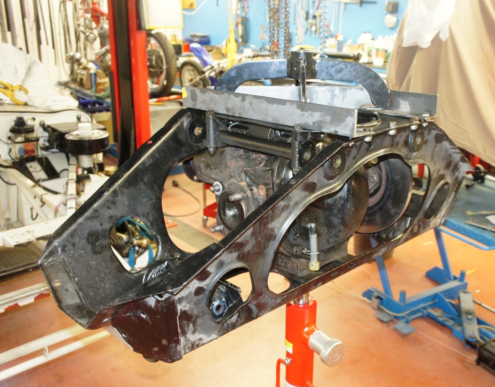
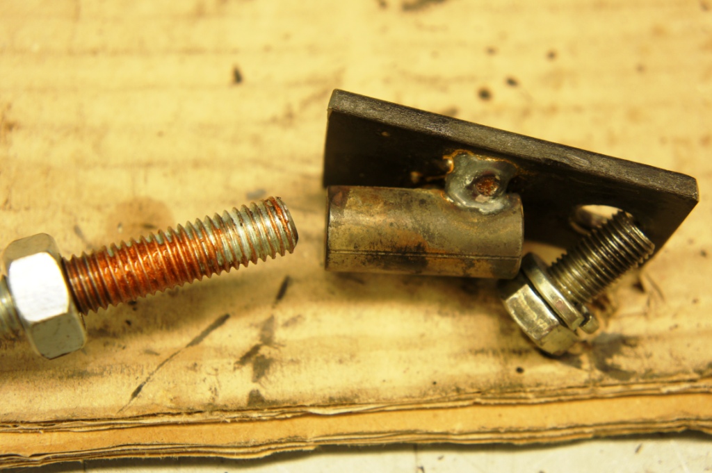
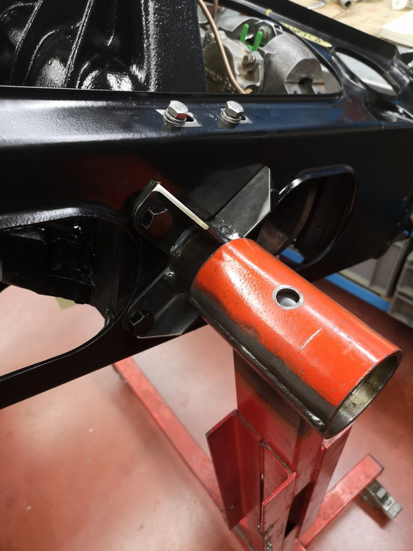
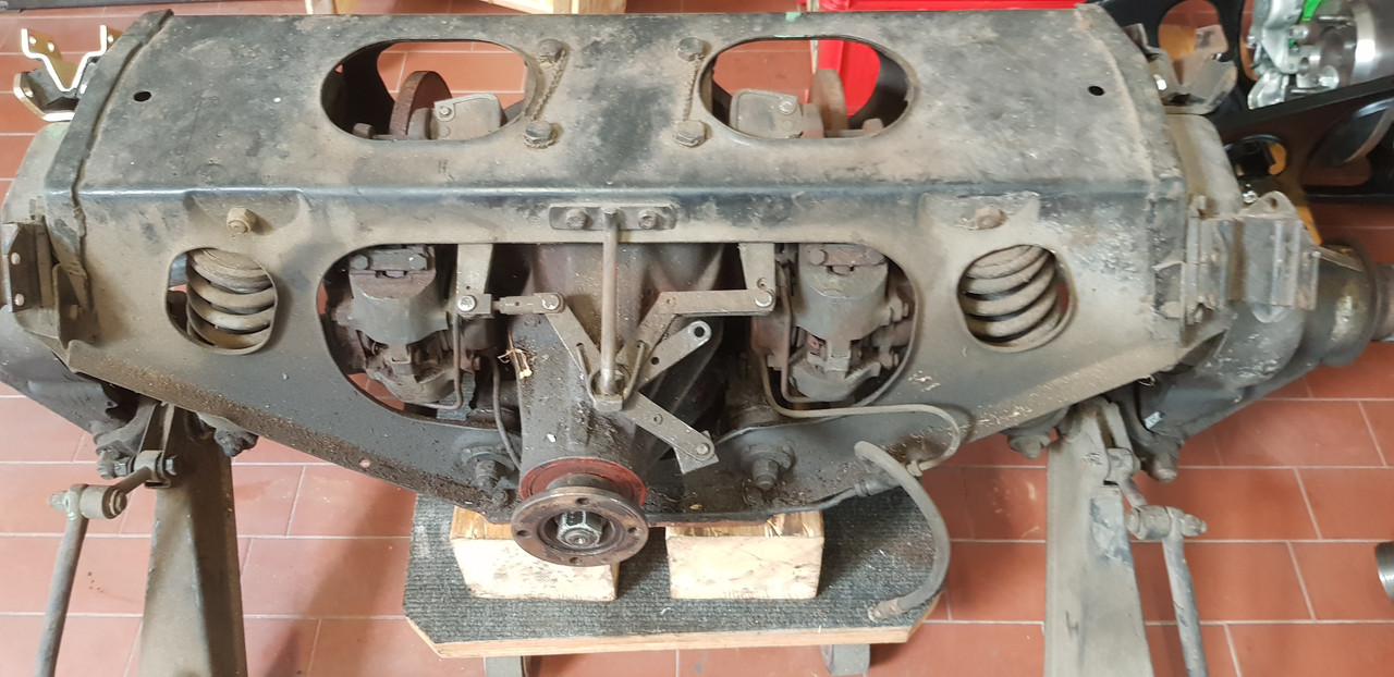
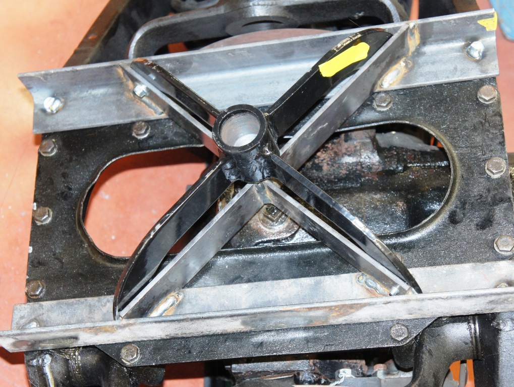
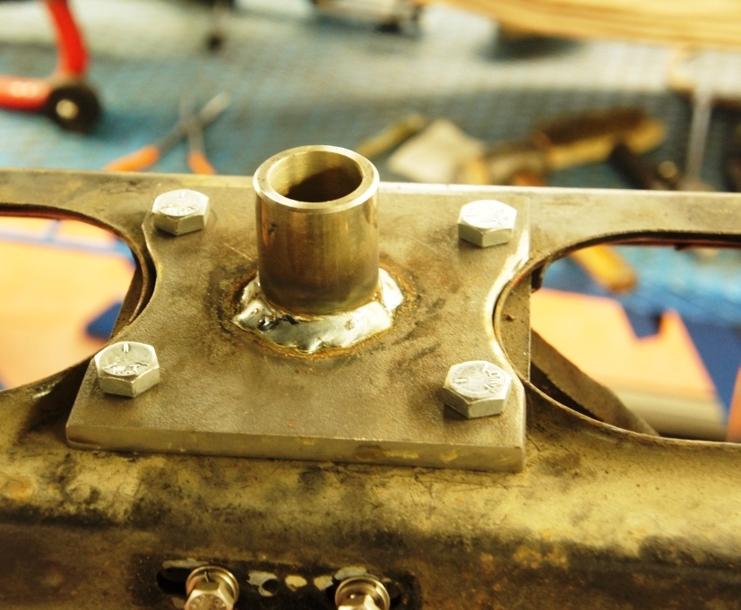
The standard supplied "crab" (as I shall call it) is just a 4-fingered scoop based around a steel slug that is bored to 30mm to accept the top of the ram, and just pops into place.
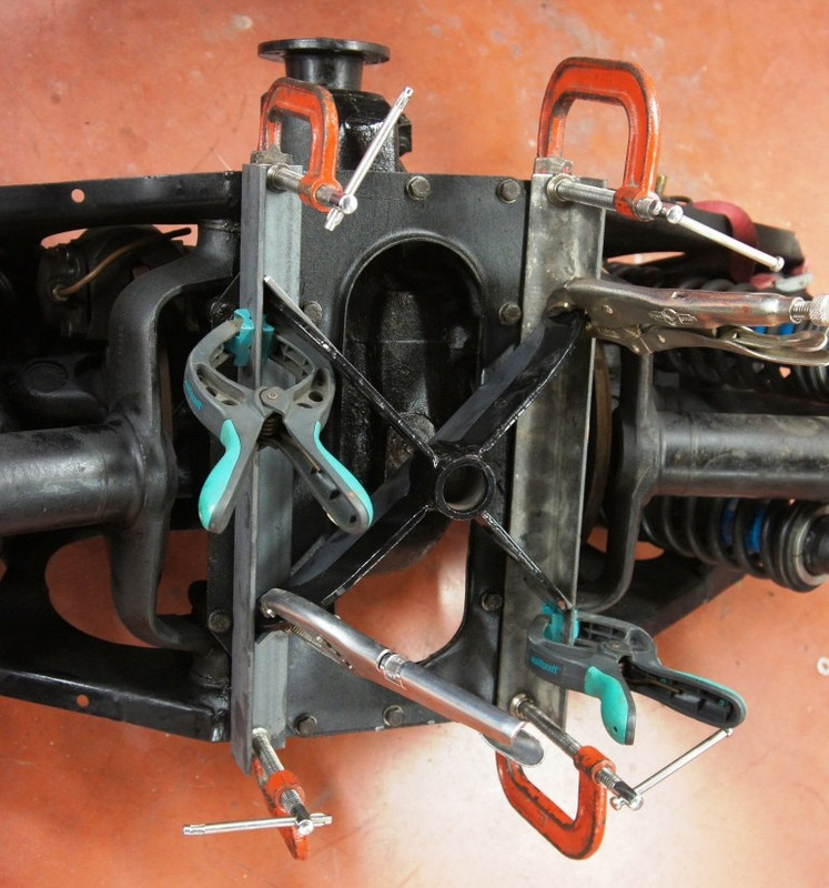
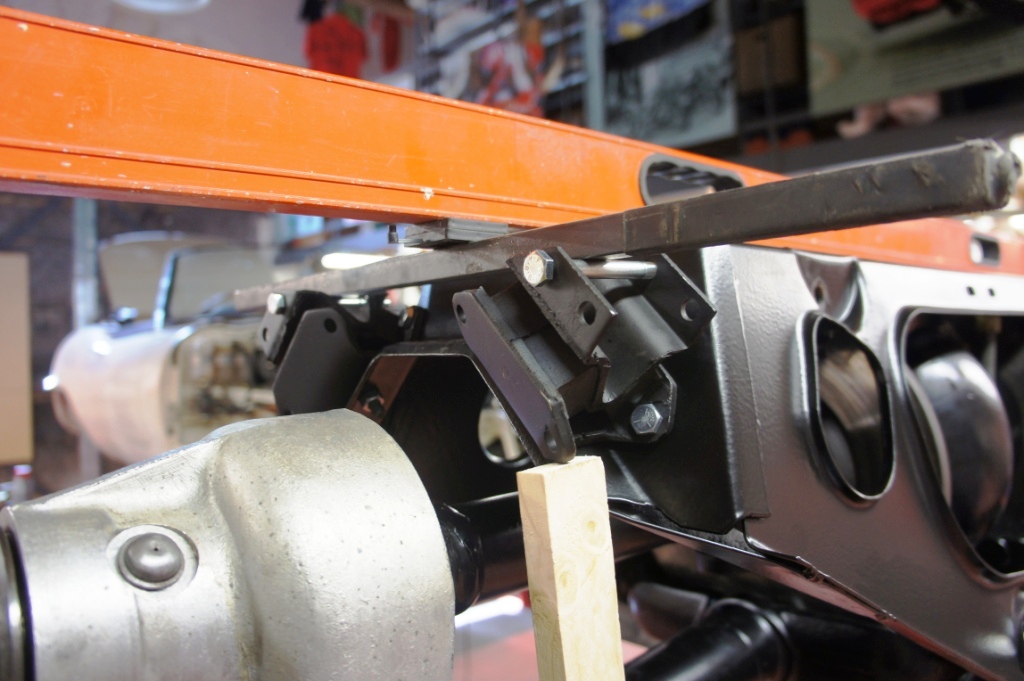
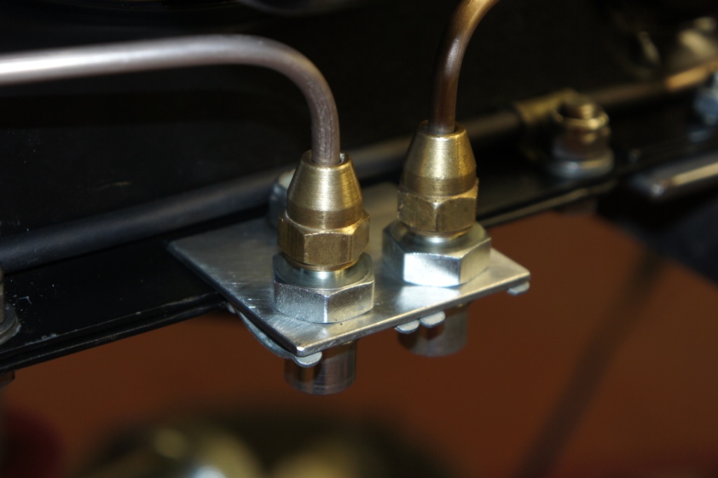
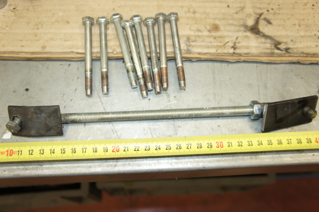
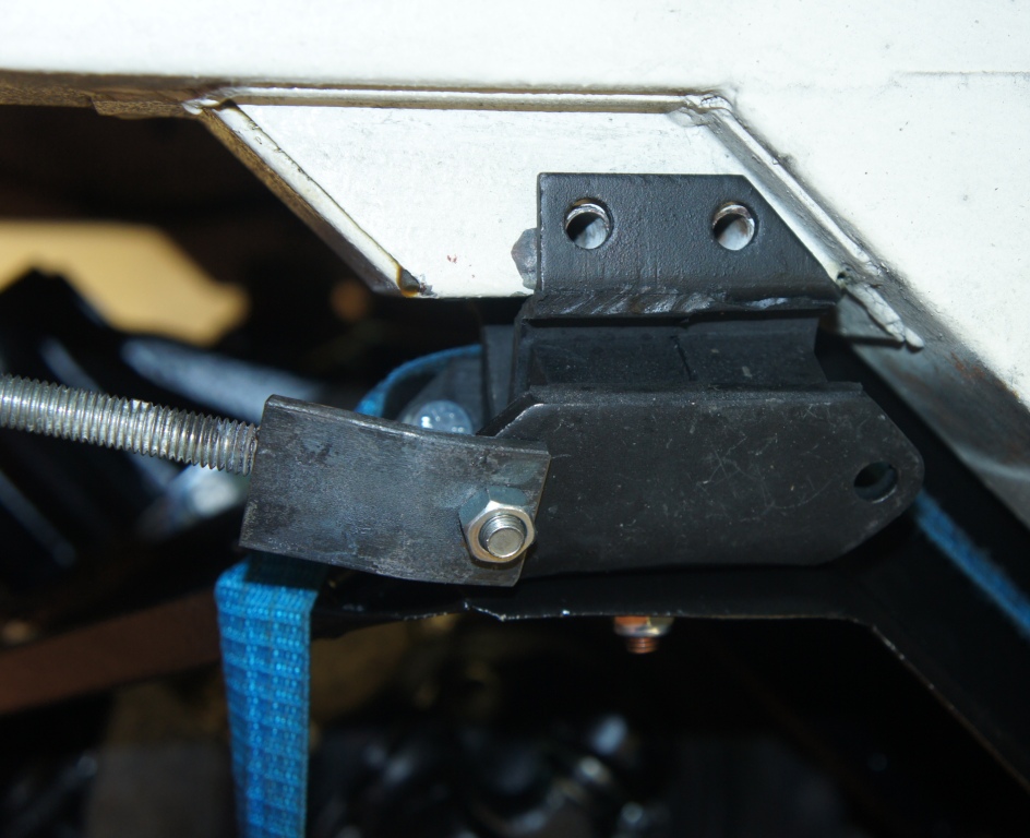
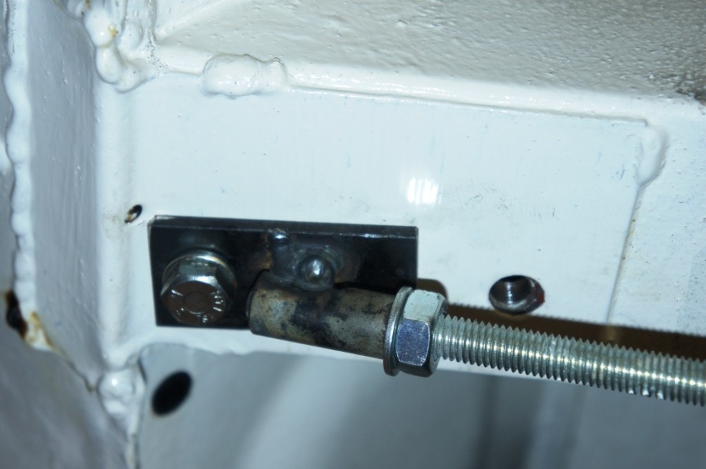
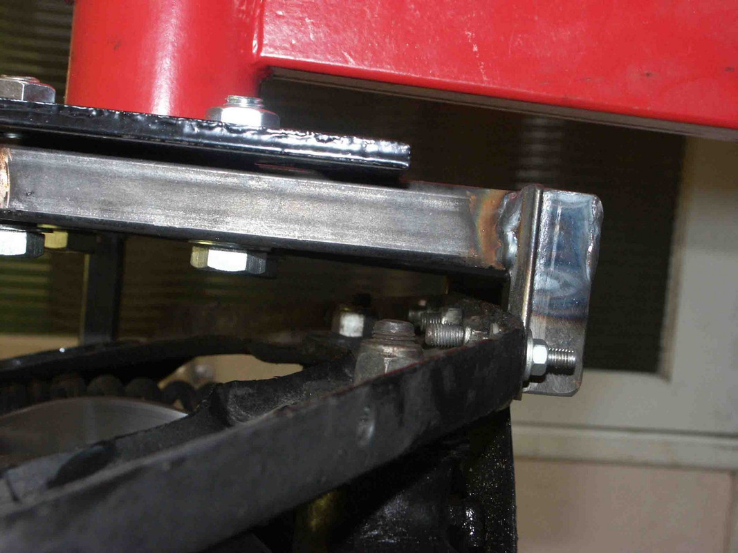
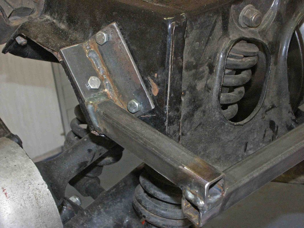
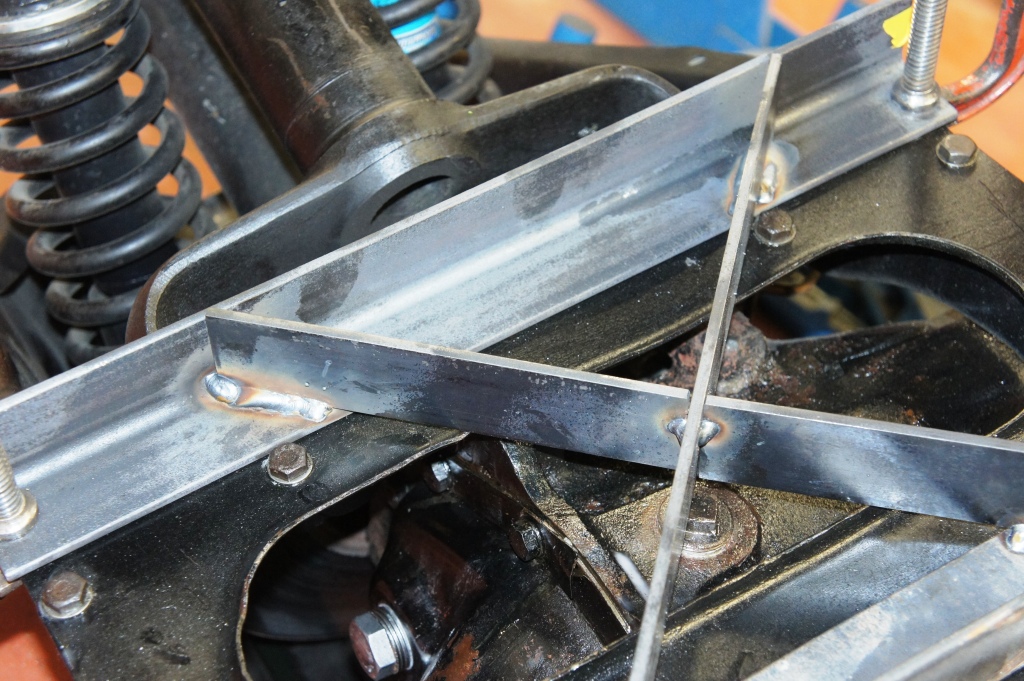
I used two bits 40x40x4 angle 410mm long to sit - conveniently - over flat areas of the IRS cradle base-plate, held in place (parallel and square) with G-cramps, coinciding with - conveniently - four spare free 5/16 holes that were un-used on my cradle, and are presumably found on all models ? If not there would be other ways of obtaining the same grip.
I set the centre of the crab about 25mm off-centre towards the front of the IRS, guessing that it was probably front-heavy, but I don't think it is that critical in practice - as soon as you take bits off the IRS you have lost any pretention of balance, and my 'prototype' works just fine.
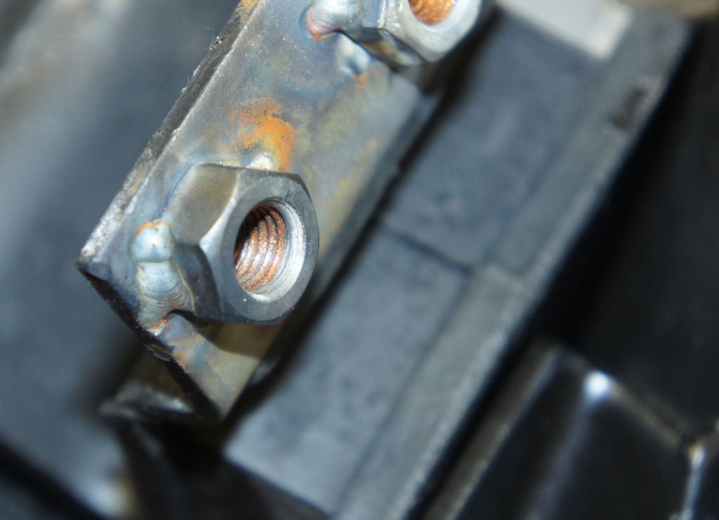
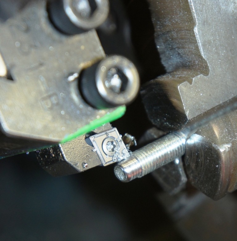
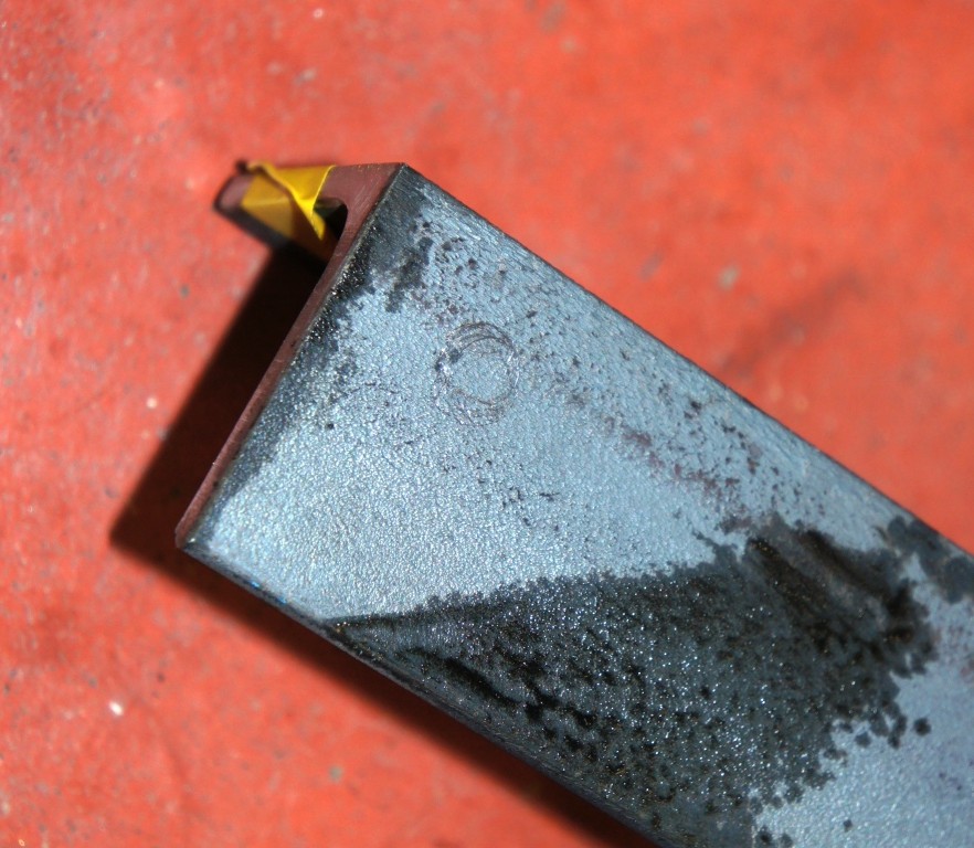
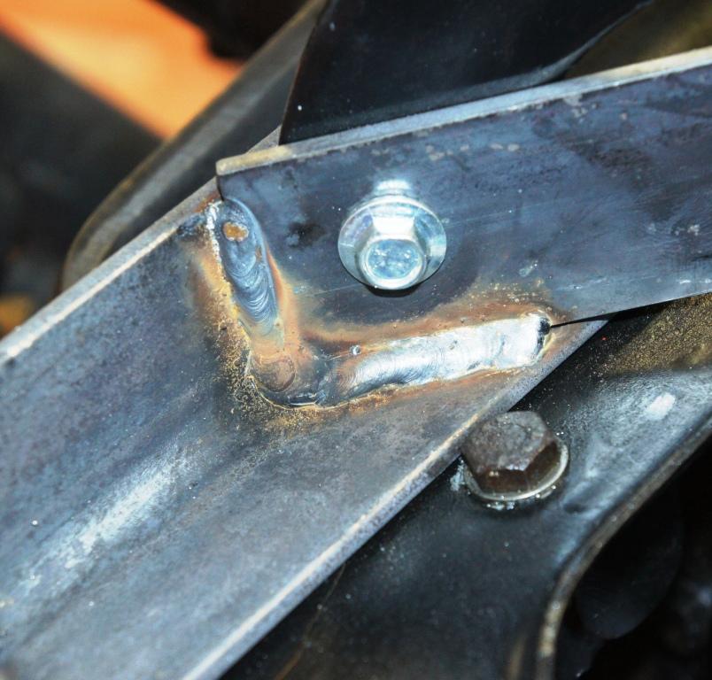
The 4-fingered crab of the jack sits comfortably under the angles, and 3 bits of suitably sized 40x4 strip, clamped temporarily to the fingers, can be welded into position.
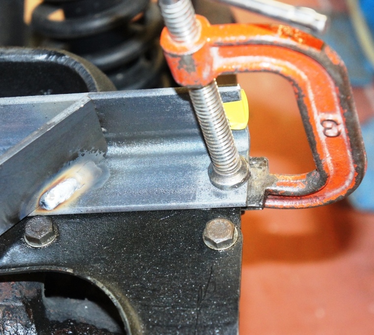
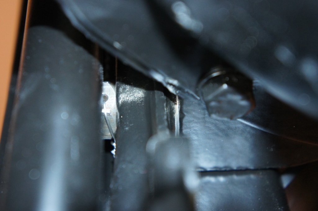
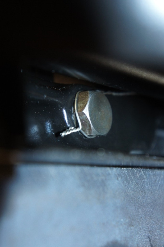
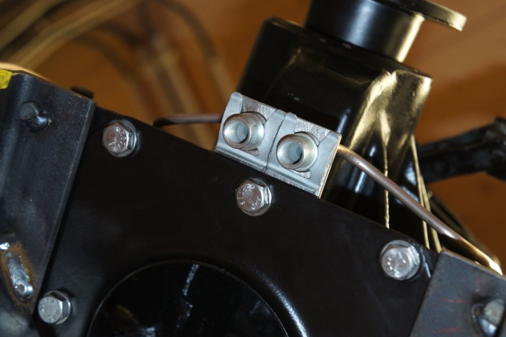
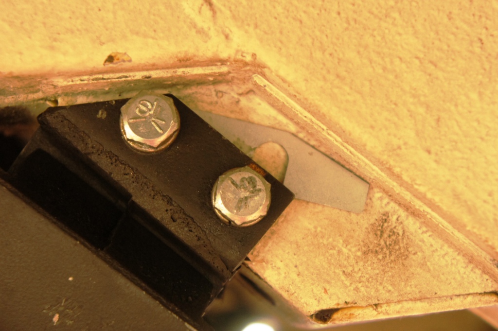
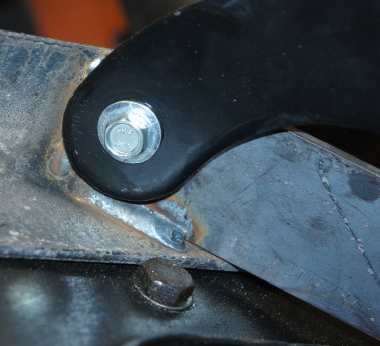
The 4 spare holes can be scribed through to give their position on the steel angles, drilled through (I did 8mm, nothing wrong with a bit of slop) then 4 x 6mm or 1/4 UNF bolts welded into place with the jig sitting on the IRS to get the right alignment.
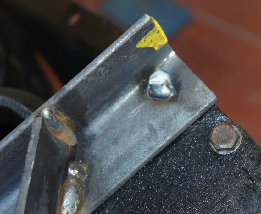
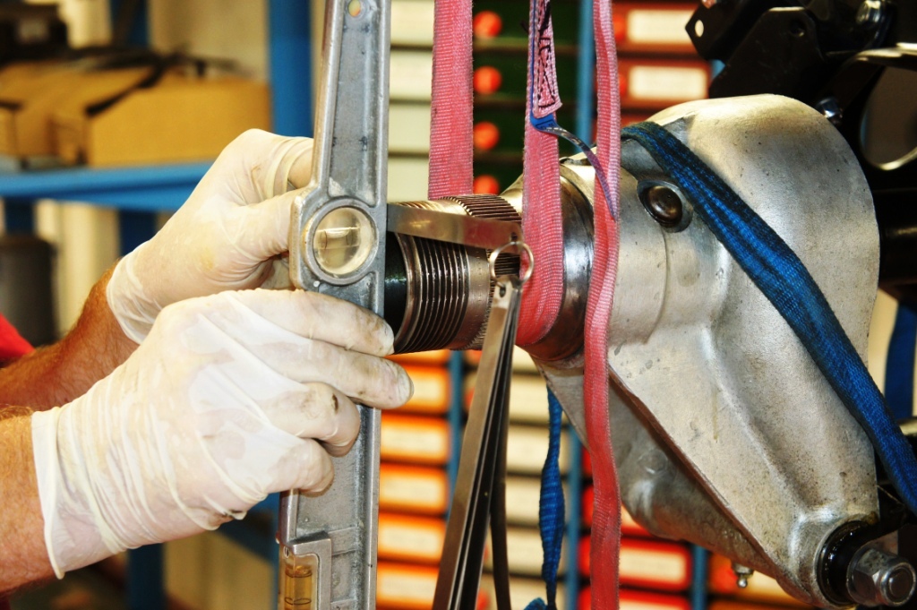
For installation and removal only, you could leave the jig at that - it can't move anywhere, being trapped by the fingers of the crab - but for overhaul and imbalanced conditions it needs a couple of drilled and tapped holes in 2 fingers so that crab and jig are inseparable.
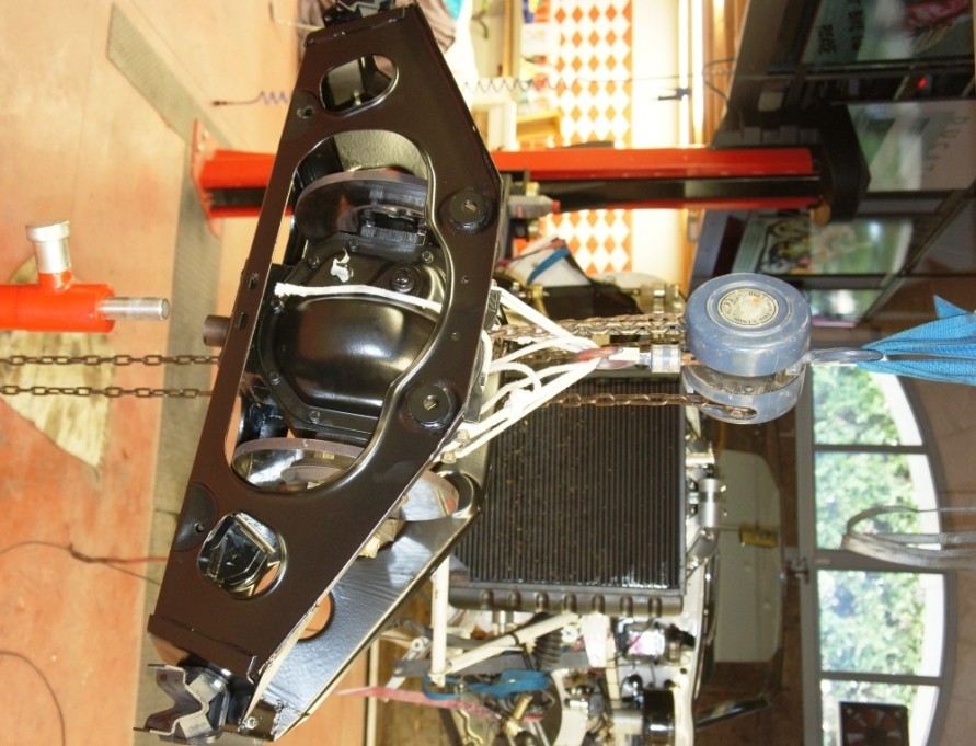
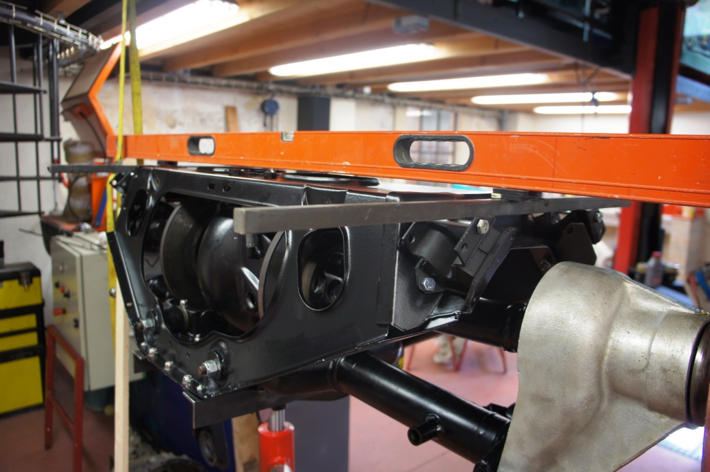
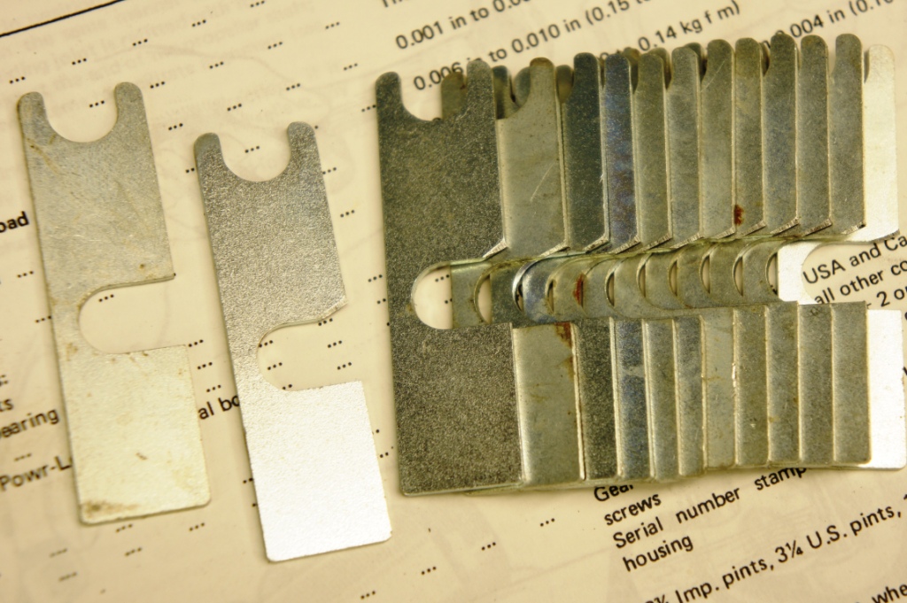
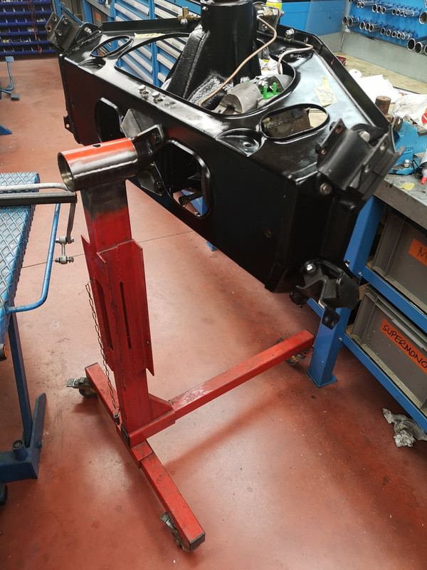
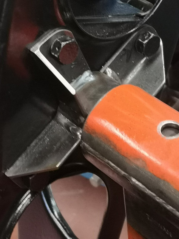
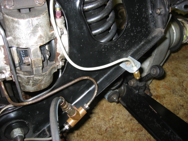
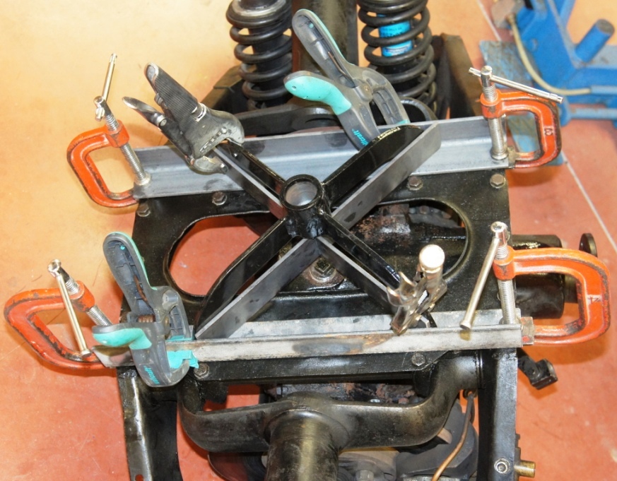
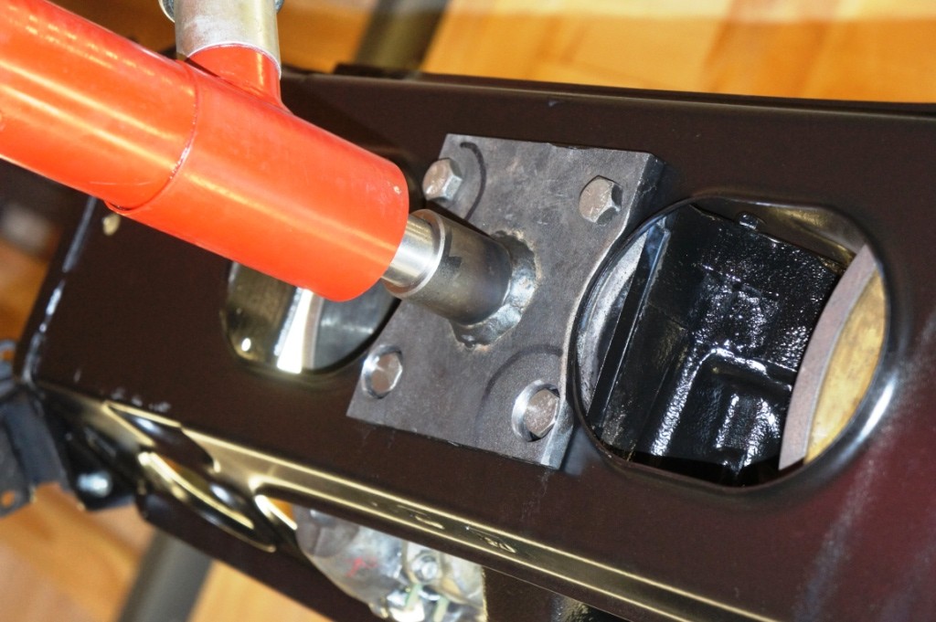
It would be perfectly possible to tweak the design, abandon the supplied crab completely, and just use another bit of 40mm steel bar bored to 30mm as a footing.
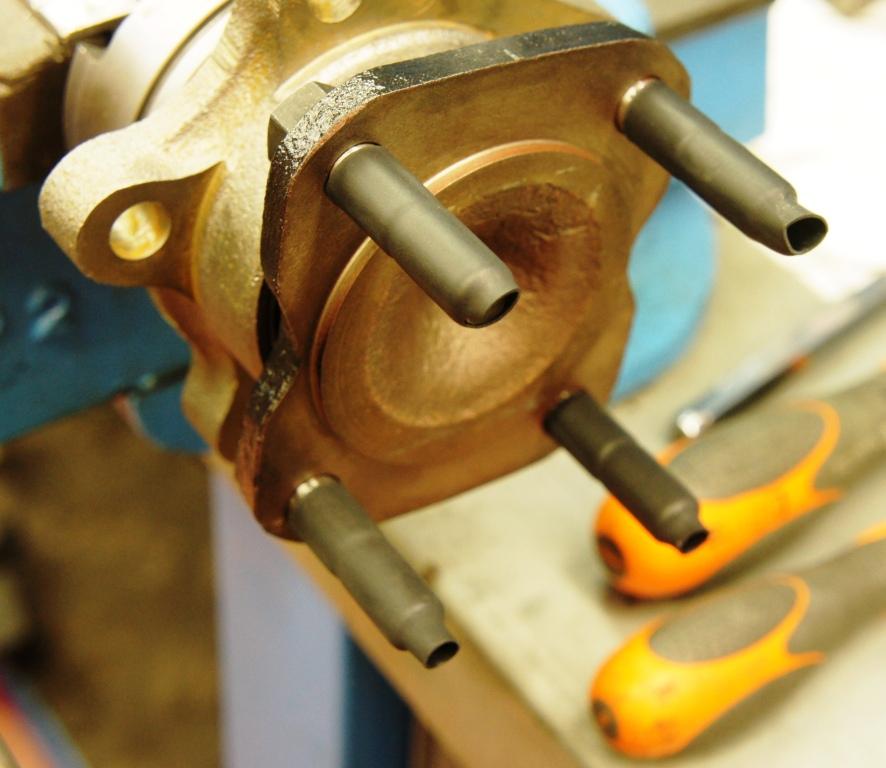
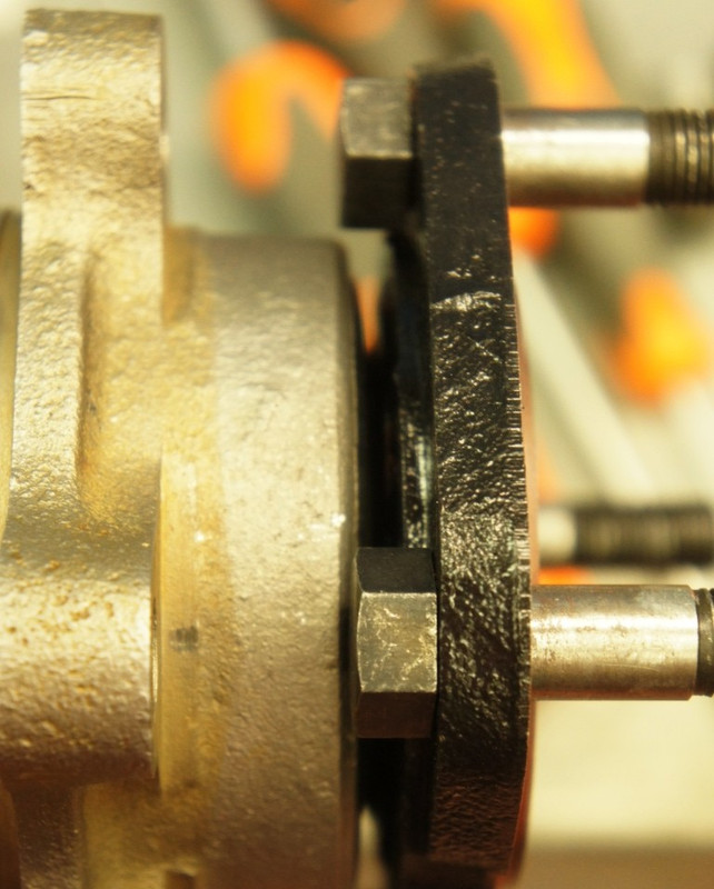
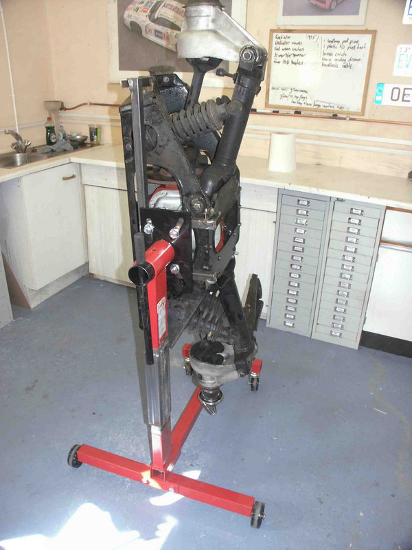
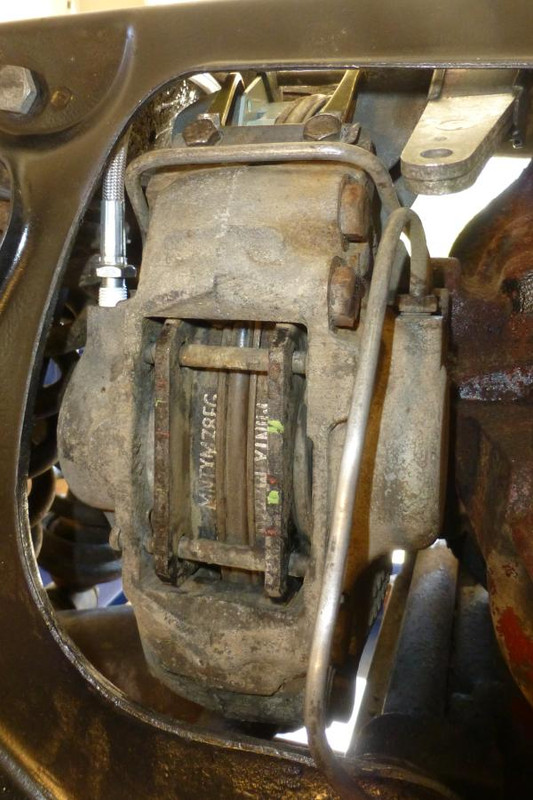
Which is what I did for the other side, since for the purposes of much of the work done on the IRS it?s actually a lot easier to work "upside down".
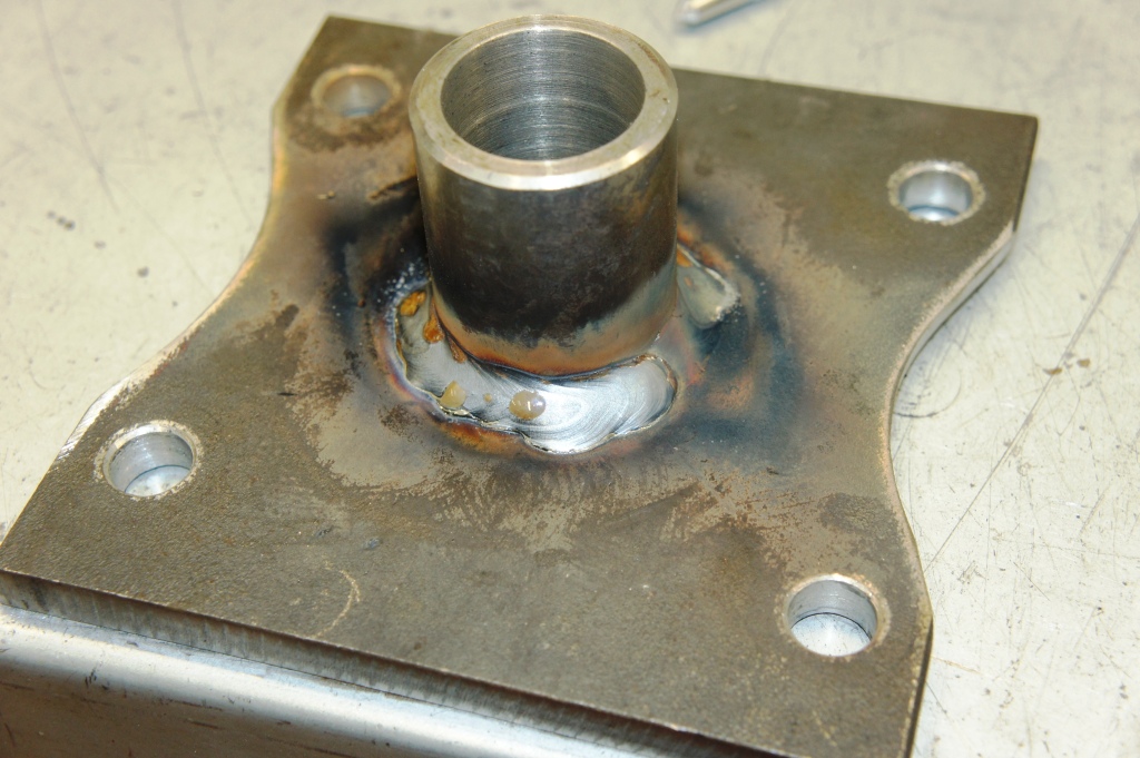
The footing of the drillings works out at a rectangle 109.5mm by 92mm from my measurements, I used a bit of 10mm(excessive) plate 140mm x 140mm, holes taken out to 13mm and used UNC bolts 1-1/2" long ; the profiles for the cage openings are tedious to cut with an angle grinder, best finished with a coarse flap-disc to get a nice radius to accompany the cage's flare, but the result looks nice.
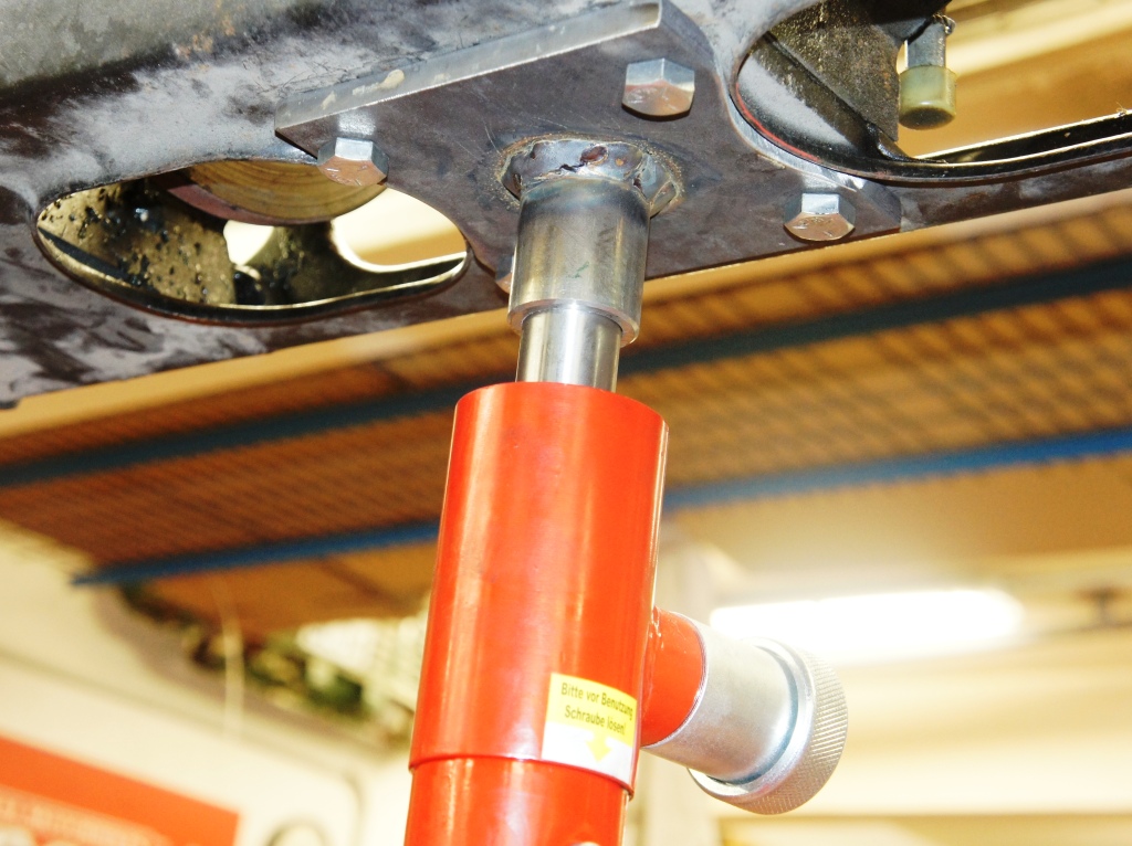
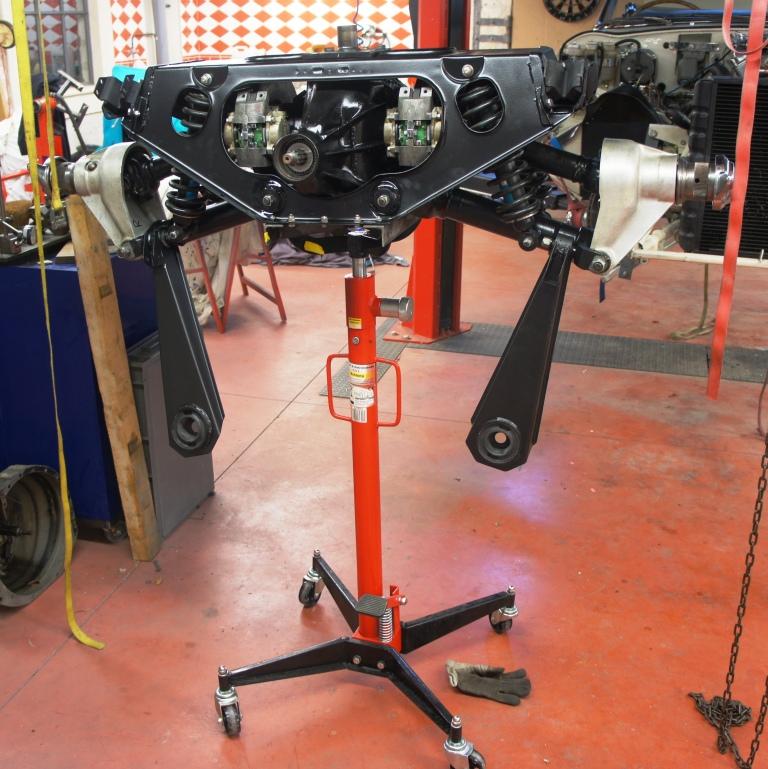
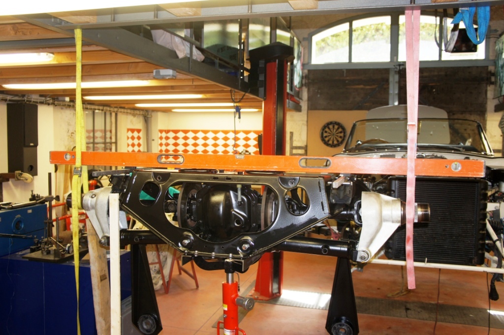
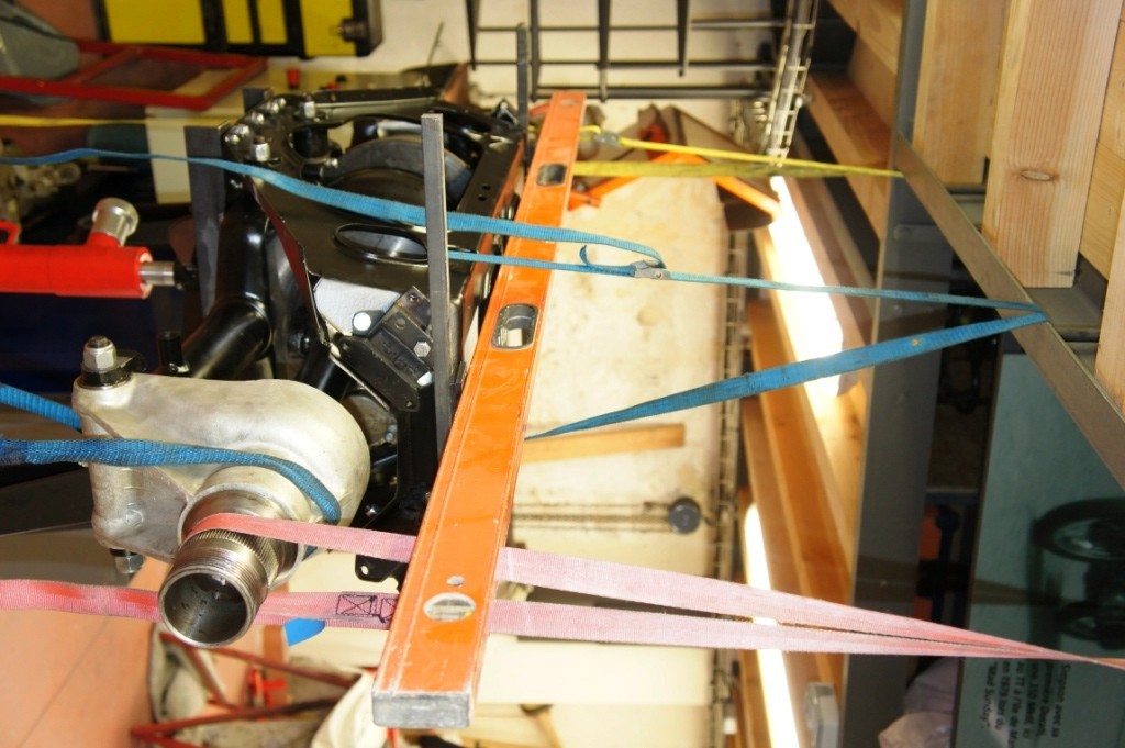
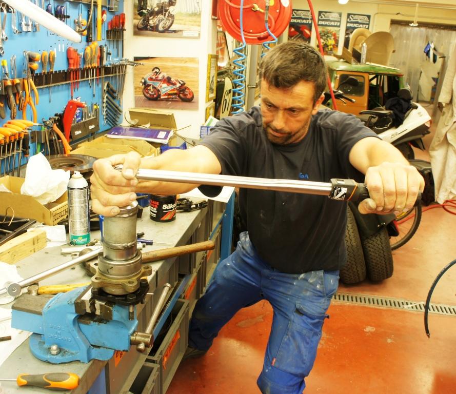
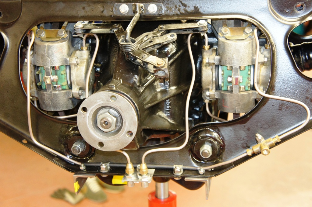
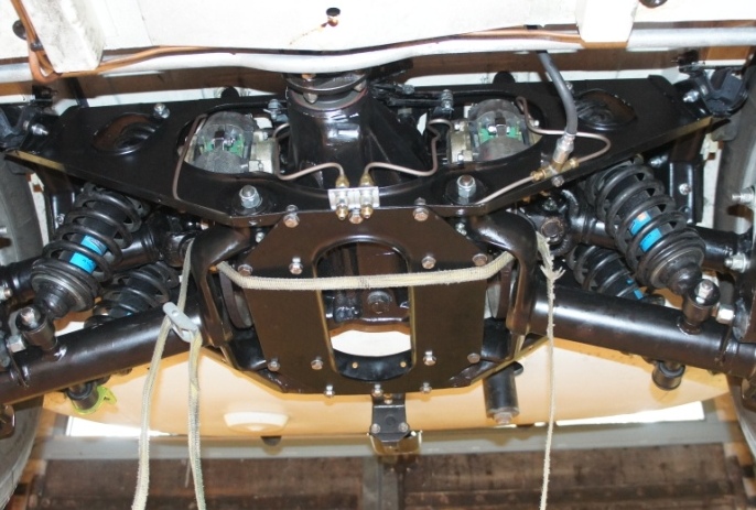
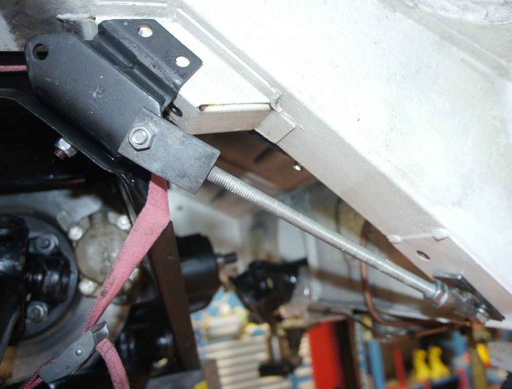
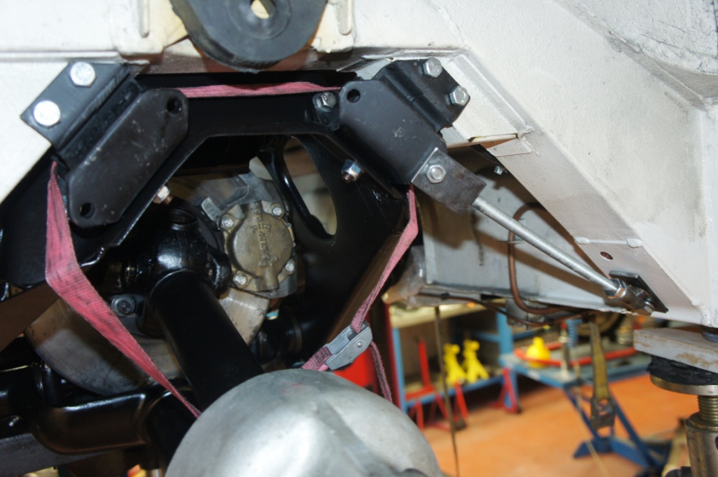
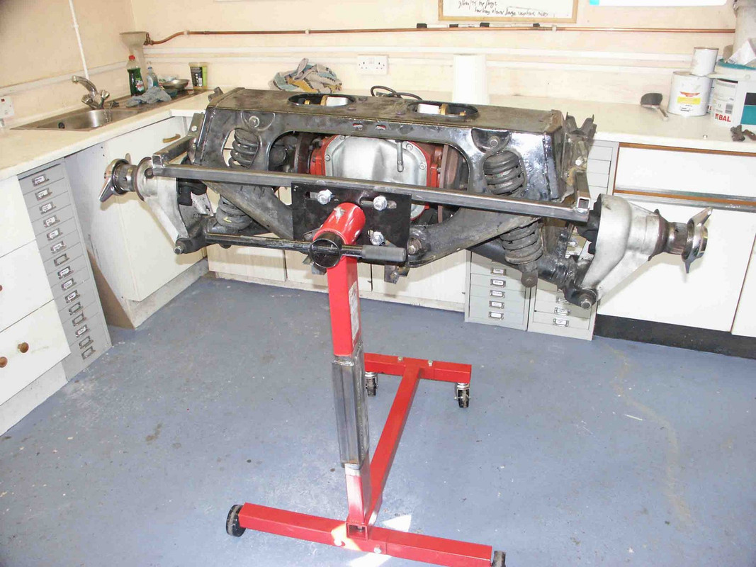
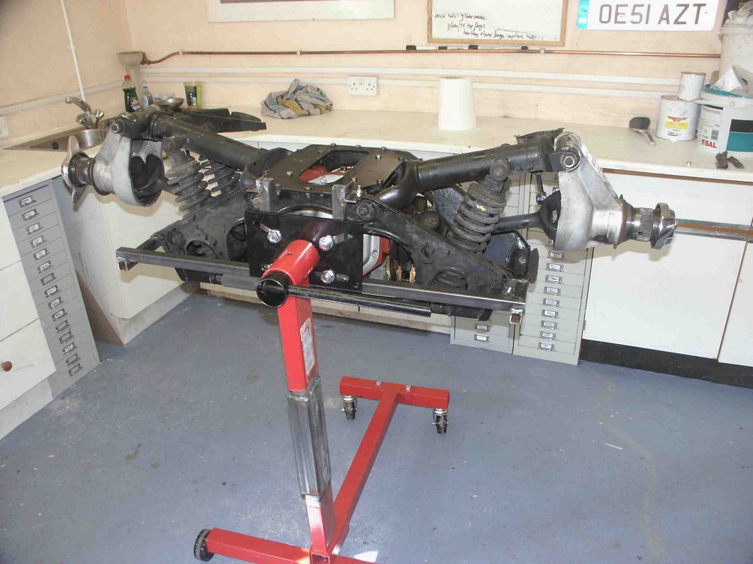
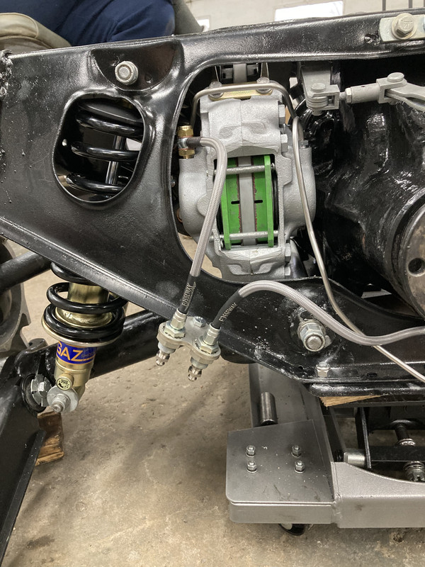
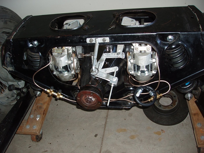
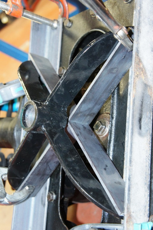
Beyond the obvious advantage of fast and safe installation and removal of the IRS, and the faculty to just wheel the thing about, this set-up is fantastic in the workshop - it can be pumped up to the height that suits best for whatever job is being done, it can be rotated with one finger to cast available light where best needed, and it remains wholly safe and within its balance "envelope" even when just one side of wishbones/drive-shaft/hub assy is removed.
Seen here before removal of the conventional lifting jig.
Next stage : an IRS-shaped rectangular drip-tray that sits snugly over the top of the hydraulic cylinder's crown, to catch parts, tools, white-spirit washing etc ......
You read it here first.