Talk about the E-Type Series 2
-
Topic author
FHCINSC
- Posts: 69
- Joined: Sun Nov 04, 2018 7:55 pm

Post
by FHCINSC » Mon Jan 21, 2019 5:00 am
Hello All
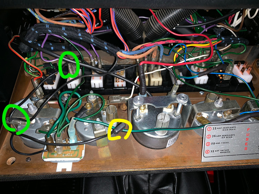
I wanted to ask about a couple of ground wires at or near the gauge cluster.
Firstly there is this cloth covered ground wire that is under the speedo/tac. In my car it had been badly grounded to a spot behind the guage cluster and had been done with a homemade wire. I read somewhere this cloth covered wire is supposed to be involved with instrument cluster grounding.
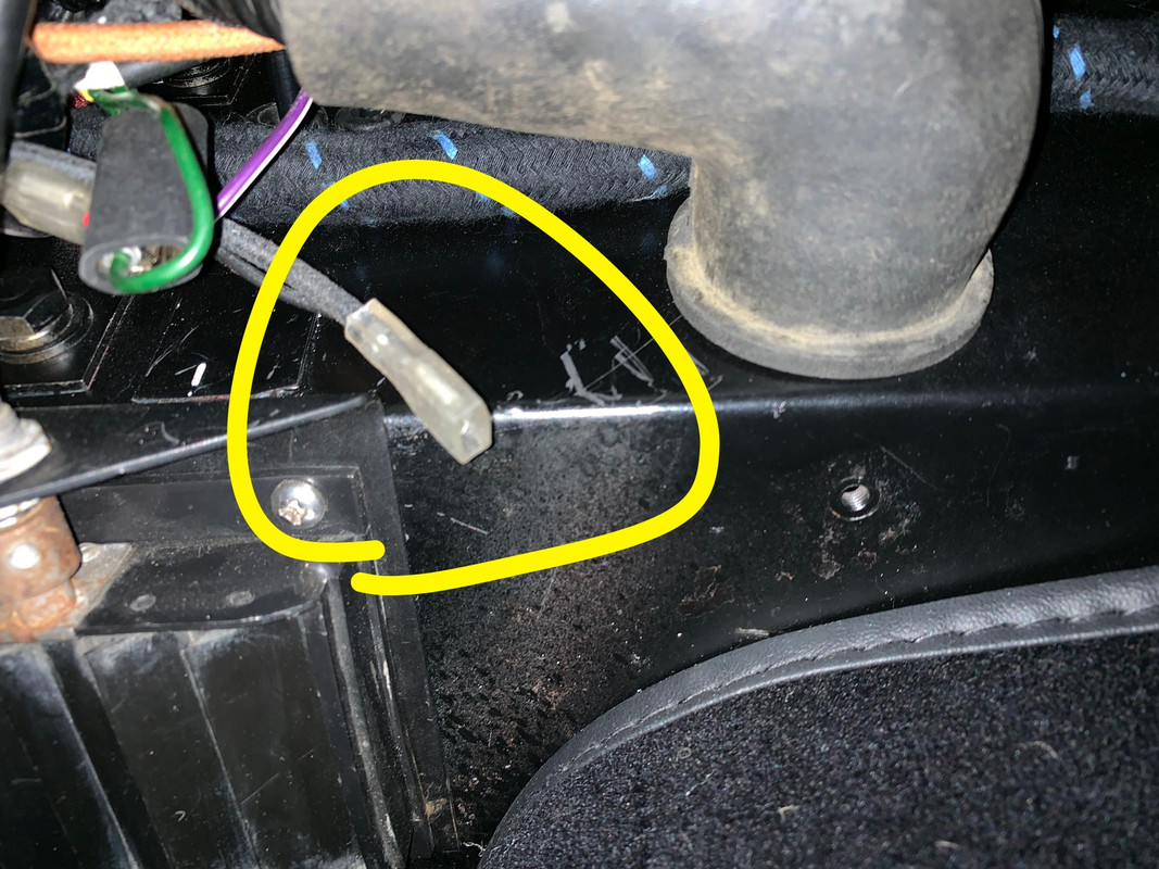
The second question is there is this non cloth covered wire coming out of the harness behind the guage cluster. It has multiple connectors on it. I’ve noted some of the connections with green circles. The one remaining connection is noted in yellow. It’s a different size connector than the ones on the instruments. Is this the connector that is supposed to ground to the metal threaded stud in the guage cluster?
Thanks as always!!
Anthony 69 FHC
-
johnetype
- Posts: 533
- Joined: Sun Feb 26, 2012 11:54 pm
- Location: Worcestershire

Post
by johnetype » Mon Jan 21, 2019 9:47 pm
My car is just slightly older than yours as I have the mercury battery operated clock, not the car battery operated clock you have and I have my original loom whereas you have a reproduction wiring loom so that said there may be differences that make my answers wrong.
I suggest the black cloth covered ground wire in your first photo could be for the earth strip that may be on the back of your tacho. If the tacho isn't grounded through that wire, or the panel light bulb holder or by its holding bracket making ground to the back of the instrument panel it won't work.
As for the non cloth covered black wire in the second photo, yes it should be connected to the stud. You can see a stud in your photo behind and between the clock and the oil pressure gauge. On an original car there is a metal "P" clip at this point grouped around a bunch of mainly red wires coming up from the loom below. On my car the black wire is attached to this stud but with an eyelet not the type of connector on your loom.
John
1969 Series 2 FHC
-
johnetype
- Posts: 533
- Joined: Sun Feb 26, 2012 11:54 pm
- Location: Worcestershire
Post
by johnetype » Mon Jan 21, 2019 9:52 pm
BTW the clock retaining bracket should be rotated by 180 degrees so its cut-outs align with the power connectors minimising the chance of a short.
John
1969 Series 2 FHC
-
Topic author
FHCINSC
- Posts: 69
- Joined: Sun Nov 04, 2018 7:55 pm
Post
by FHCINSC » Mon Jan 21, 2019 9:58 pm
Advice/Wisdom level=Final Boss! Thank you so much.
johnetype wrote: ↑Mon Jan 21, 2019 9:52 pm
BTW the clock retaining bracket should be rotated by 180 degrees so its cut-outs align with the power connectors minimising the chance of a short.
-
mark10337
- Posts: 756
- Joined: Wed Jul 22, 2015 11:11 am
- Location: Switzerland

Post
by mark10337 » Tue Jan 22, 2019 10:18 am
The first one goes to a lucas tab attached to the bulkead, pretty much directly behind the rev counter.
I changed this to an ring, as the tab can come off.
-Mark
1969 Series 2 OTS, Regency Red
'Life's to short to drive a boring car'


