


Hello.
I want to test my series one otter switch. It sits on top of the radiator and has two connectors going to it.. It is a twin fan radiator.
If I disconnect both connectors and connect them together by a copper wire should that start the fans?
Many thanks,
John
Otter switch test
#1 Otter switch test
Last edited by Johnlowe on Sun May 31, 2026 2:27 pm, edited 2 times in total.
| Link: | |
| BBcode: | |
| HTML: | |
| Hide post links |
#2 Re: Otter switch test
With the ignition on, yes.
Simon
62 3.8 FHC
91 Porsche 928GT
Find me on Instagram and Facebook @oldcarfixer
62 3.8 FHC
91 Porsche 928GT
Find me on Instagram and Facebook @oldcarfixer
| Link: | |
| BBcode: | |
| HTML: | |
| Hide post links |
#3 Re: Otter switch test
If you do that, you've tested everything except the Otter switch.
kind regards
Marek
kind regards
Marek
| Link: | |
| BBcode: | |
| HTML: | |
| Hide post links |
#4 Re: Otter switch test
Matekh, at the moment the fans do not work, hence connecting the two otter switch wires to see if they come on. If they do it means the other switch is not working.
| Link: | |
| BBcode: | |
| HTML: | |
| Hide post links |
#5 Re: Otter switch test
Hello,
I have connected a wire across the two spade connectors and no fans come on. I noticed a small spark each time I did this and when I reconnected them to the otter switch. I also checked with a multimeter across the two connectors and got 12 volts. One connector presumably is positive and the other negative? Is that right?
Am at a loss as to what is wrong. I find this a black art so if anyone has any suggestions please let me know!
Many thanks,
John
I have connected a wire across the two spade connectors and no fans come on. I noticed a small spark each time I did this and when I reconnected them to the otter switch. I also checked with a multimeter across the two connectors and got 12 volts. One connector presumably is positive and the other negative? Is that right?
Am at a loss as to what is wrong. I find this a black art so if anyone has any suggestions please let me know!
Many thanks,
John
| Link: | |
| BBcode: | |
| HTML: | |
| Hide post links |

#6 Re: Otter switch test
Are your fans wired through a relay or directly to fuse No6?
Danny
1962 S1 3.8 FHC (1012/1798)
2015 Range Rover Sport SVR
"Experience is something you don't get until just after you need it."
1962 S1 3.8 FHC (1012/1798)
2015 Range Rover Sport SVR
"Experience is something you don't get until just after you need it."
| Link: | |
| BBcode: | |
| HTML: | |
| Hide post links |

#7 Re: Otter switch test
John,
The otter switch merely completes the circuit (earth/ground on my S1) once the temperature goes too high, bringing the fan(s) on via the relay (my car).
Joining your 2 otter switch wires together merely takes the otter switch out of the fault finding equation at this stage, which is good. Are the fans spinning freely, by hand?
With wires joined and ignition on try moving fans with a long screwdriver, to see if they start up, DONT put your fingers in there! If nothing happens, you need to locate your relay and investigate:
1. There is a 12v ignition source.
2. A permanent 12 source.
3. A ground/earth (via otter switch wires)
Also at the relay you will find fan power wires, these send 12v to the fan(s) once the relay is made(on) and when otter switch completes the earth circuit. With the relay out, you can supply a direct12v feed to the fan motor wire here. This will ultimately test the fan motor directly and so long as the fan motor has a good earth/ground, it should run if its good. Check fan motor earth/ground wires too. These should be separate and at a good chassis ground point.
Do you have a fan override switch in the car?
What car do you have as you mention S1 otter and twin fans
The otter switch merely completes the circuit (earth/ground on my S1) once the temperature goes too high, bringing the fan(s) on via the relay (my car).
Joining your 2 otter switch wires together merely takes the otter switch out of the fault finding equation at this stage, which is good. Are the fans spinning freely, by hand?
With wires joined and ignition on try moving fans with a long screwdriver, to see if they start up, DONT put your fingers in there! If nothing happens, you need to locate your relay and investigate:
1. There is a 12v ignition source.
2. A permanent 12 source.
3. A ground/earth (via otter switch wires)
Also at the relay you will find fan power wires, these send 12v to the fan(s) once the relay is made(on) and when otter switch completes the earth circuit. With the relay out, you can supply a direct12v feed to the fan motor wire here. This will ultimately test the fan motor directly and so long as the fan motor has a good earth/ground, it should run if its good. Check fan motor earth/ground wires too. These should be separate and at a good chassis ground point.
Do you have a fan override switch in the car?
What car do you have as you mention S1 otter and twin fans
Steve
1965 S1 4.2 FHC (early)

1965 S1 4.2 FHC (early)
| Link: | |
| BBcode: | |
| HTML: | |
| Hide post links |
#8 Re: Otter switch test
Thanks for replies, really appreciated.
Car is a 1968 FHC. Called Series 1.5, but Heritage Certificate classes its Series 1. Built July 1968. Has factory fitted twin fans . They were working ok until recently. Have had fuse fail servers times on the past year. Could that be a clue. Both fans turn easily by hand. Will try connect directly to 12 volts source.
Many thanks.
Car is a 1968 FHC. Called Series 1.5, but Heritage Certificate classes its Series 1. Built July 1968. Has factory fitted twin fans . They were working ok until recently. Have had fuse fail servers times on the past year. Could that be a clue. Both fans turn easily by hand. Will try connect directly to 12 volts source.
Many thanks.
| Link: | |
| BBcode: | |
| HTML: | |
| Hide post links |


#9 Re: Otter switch test
Heritage cert is correct, there was no such thing officially as a Series 1.5.
Randall Botha
'64 3.8 fhc & '51 Mk 7 (now sold), previously 3.8 S-type x2, 2.4 Mk 1, XJ6 S1.
'64 3.8 fhc & '51 Mk 7 (now sold), previously 3.8 S-type x2, 2.4 Mk 1, XJ6 S1.
| Link: | |
| BBcode: | |
| HTML: | |
| Hide post links |
#10 Re: Otter switch test
John,
The Series 1 from 1968 was mostly as per Series 2. A sort of half-way model.
Your cooling is the same as a Series 2. A really good wiring diagram is in the Knowledge base here:
https://www.dropbox.com/s/kn0ggc2neu3vf ... m.bmp?dl=1
If you have been getting fuses blowing, then you definitely have a wiring issue. Your fans will be enabled via a Lucas relay mounted on the picture frame under the bonnet. Check all the wiring around that area and trace the wires back to the otter switch.
As already mentioned, the otter switch just supplies earth to the relay coil when the coolant temp goes too high.
The Series 1 from 1968 was mostly as per Series 2. A sort of half-way model.
Your cooling is the same as a Series 2. A really good wiring diagram is in the Knowledge base here:
https://www.dropbox.com/s/kn0ggc2neu3vf ... m.bmp?dl=1
If you have been getting fuses blowing, then you definitely have a wiring issue. Your fans will be enabled via a Lucas relay mounted on the picture frame under the bonnet. Check all the wiring around that area and trace the wires back to the otter switch.
As already mentioned, the otter switch just supplies earth to the relay coil when the coolant temp goes too high.
Simon
62 3.8 FHC
91 Porsche 928GT
Find me on Instagram and Facebook @oldcarfixer
62 3.8 FHC
91 Porsche 928GT
Find me on Instagram and Facebook @oldcarfixer
| Link: | |
| BBcode: | |
| HTML: | |
| Hide post links |
#11 Re: Otter switch test
Hello kind helpers.
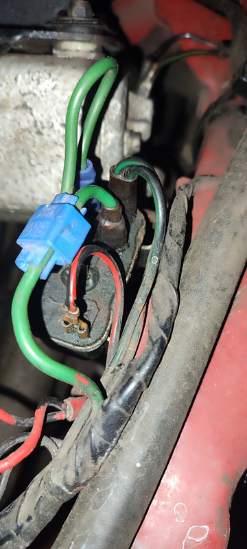
Some success but not there yet! As an experiment I moved the green wire spade connector on the relay, (please see photo), to an adjacent connector and the fans came on! Bingo! But they stay on all the time with the ignition switched on! What does this suggest? Is it a faulty relay?
Any help gratefully received.
John
Some success but not there yet! As an experiment I moved the green wire spade connector on the relay, (please see photo), to an adjacent connector and the fans came on! Bingo! But they stay on all the time with the ignition switched on! What does this suggest? Is it a faulty relay?
Any help gratefully received.
John
| Link: | |
| BBcode: | |
| HTML: | |
| Hide post links |


#12 Re: Otter switch test
Hi John....just guessing and moveing wires around isn't a great way to fault find and risks damage and burnt out wires....far better to use a multimeter and test out what you have...useing a circuit diagram..it looks like someone has been in there and altered the wireing as if isnt original looking...Steve
Steve
69 S2 2+2 (sold) ..Realm C type replica, 1960 xk150fhc
69 S2 2+2 (sold) ..Realm C type replica, 1960 xk150fhc
| Link: | |
| BBcode: | |
| HTML: | |
| Hide post links |
#13 Re: Otter switch test
I've had the car nearly 50 years! Second owner! Never touched anything in that area and fans have always worked so can't feel it wasn't an original fitting. Can't be sure though.
Awaiting new relay and will install and wire as before. Hopefully will work.
John
Awaiting new relay and will install and wire as before. Hopefully will work.
John
| Link: | |
| BBcode: | |
| HTML: | |
| Hide post links |
#14 Re: Otter switch test
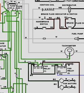
Hi John, according to the S1.5 wiring diagram your two Black/Green wires power (12v) the two fans and should connect to terminal C1 on that relay.
Your ignition 12v Green comes from fuse No.6 to terminal C2 on same relay. Did you connect these two wires (by luck) as this would bring the fans on? This proves the wiring from the relay to the fans is ok.
Your Black and Red wire fitted to W1 relay terminal, goes to the otter switch.
I would disconnect this temporarily, switch ignition on and touch a short ground (neg) cable to this W1 terminal. With correct wiring and good relays, the fans should run. This proves the relay is correctly operating with a ground switch - the job of a good and serviceable otter switch when hot hot.
The wiring diagram shows a second relay so search for this and trace wiring ( C1 to C1, C2 to C2 and W1 to earth/ground). It also shows a White/Blue (WU) wire on second relay that goes to Air Con Switch Control, if fitted.
Your ignition 12v Green comes from fuse No.6 to terminal C2 on same relay. Did you connect these two wires (by luck) as this would bring the fans on? This proves the wiring from the relay to the fans is ok.
Your Black and Red wire fitted to W1 relay terminal, goes to the otter switch.
I would disconnect this temporarily, switch ignition on and touch a short ground (neg) cable to this W1 terminal. With correct wiring and good relays, the fans should run. This proves the relay is correctly operating with a ground switch - the job of a good and serviceable otter switch when hot hot.
The wiring diagram shows a second relay so search for this and trace wiring ( C1 to C1, C2 to C2 and W1 to earth/ground). It also shows a White/Blue (WU) wire on second relay that goes to Air Con Switch Control, if fitted.
Last edited by caveman on Wed May 07, 2025 9:55 pm, edited 1 time in total.
Steve
1965 S1 4.2 FHC (early)
1965 S1 4.2 FHC (early)
| Link: | |
| BBcode: | |
| HTML: | |
| Hide post links |
#15 Re: Otter switch test
The scotch lock and blue crimp connector arnt factory..Steve
Steve
69 S2 2+2 (sold) ..Realm C type replica, 1960 xk150fhc
69 S2 2+2 (sold) ..Realm C type replica, 1960 xk150fhc
| Link: | |
| BBcode: | |
| HTML: | |
| Hide post links |
#16 Re: Otter switch test
Also a sign of a bodge/short cut. Do it once, do it properly I say.
Steve
1965 S1 4.2 FHC (early)
1965 S1 4.2 FHC (early)
| Link: | |
| BBcode: | |
| HTML: | |
| Hide post links |
#17 Re: Otter switch test
Three points.
The fan relay on the picture frame has five connectors, not three.
My Haynes wiring diagram says two relays if the car has air conditioning, which if course mine doesn't.
The fuse diagram in the car's drop down dash compartment shows fuse number 6 for fan relay
Very confusing, for me that is.
The fan relay on the picture frame has five connectors, not three.
My Haynes wiring diagram says two relays if the car has air conditioning, which if course mine doesn't.
The fuse diagram in the car's drop down dash compartment shows fuse number 6 for fan relay
Very confusing, for me that is.
| Link: | |
| BBcode: | |
| HTML: | |
| Hide post links |
#18 Re: Otter switch test
Steve, many thanks for your input.
Just want to check, my relay has 5 connectors, the diagram you sent appears to show three. Am I right that some early e types had a three connector relay and later had five?
I have ordered a five one and as I said will try it.
Again thanks for your kind interest and help.
John
Just want to check, my relay has 5 connectors, the diagram you sent appears to show three. Am I right that some early e types had a three connector relay and later had five?
I have ordered a five one and as I said will try it.
Again thanks for your kind interest and help.
John
| Link: | |
| BBcode: | |
| HTML: | |
| Hide post links |
#19 Re: Otter switch test
Steve, just found this if you look at it. It appears to give some clarity on my situation.....
https://forums.jag-lovers.com/t/series- ... lay/436215
Cheers, John
https://forums.jag-lovers.com/t/series- ... lay/436215
Cheers, John
| Link: | |
| BBcode: | |
| HTML: | |
| Hide post links |
#20 Re: Otter switch test
A three pin relay is just a cut down version of the five pin relay with the c3 pin missing and the c2 pin doubling up as the w2 pin via an internal connection. To make the five pin relay work here, someone doubled up the green wire with the blue clip so the new (external) w2 pin could connect to a green wire, just like it would have had if it had been a 3 pin relay.
These relays are pretty bullet proof and if you have 65-70ohms between w2 and w1 (5 pin version) or between c2 and w1 (3 pin version) then it's probably just dirty contacts inside the relay that need cleaning.
kind regards
Marek
These relays are pretty bullet proof and if you have 65-70ohms between w2 and w1 (5 pin version) or between c2 and w1 (3 pin version) then it's probably just dirty contacts inside the relay that need cleaning.
kind regards
Marek
| Link: | |
| BBcode: | |
| HTML: | |
| Hide post links |